
Page 325 - Integrated Wireless Propagation Models
P. 325
I n - B u i l d i n g ( P i c o c e l l ) P r e d i c t i o n M o d e l s 303
Measured data with shadow effect
y
1 0 0 - X X x Same floor
1 0 1 [ X � 1 floor
1 0 2 1 0 X 0 2 floors
I
1 0 3 - �
((}
�
� :: [ 0 X 0 X
.9.
..c
;f 1 0 6
� : : �
1 0 9 r
1 1 0 ------�------�------�------�--���--��-L------� X
1 1 . 1 1.2 1.3 1.4 1.5 1.6 1.7
Distance in dec (10x meters)
y Measured data without shadow effect
93 - X
x Same floor
94 - X X � 1 floor
0 2 floors
95 1 0
1
96 � 0 0 � x o
!?5 97 [
-�
gJ 98 -
.9. I
� 99 1
1 0 0 0
I
1 0 1 -
1 0 2 1
1 0 3 �----�------��----�------����-L------�------- X
1 . 1 1.2 1.3 1.4 1.5 1.6 1.7 1.8
Distance in dec (10x meters)
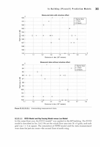
FIGURE 5.3.2.3.2.1 l n terbuilding measurement data.
3
5.3. . 1 . 1 FDTD Model and Ray Tracing Model versus Lee Model
In this same-floor case, the FDTD modeP7 was applied in the RP building. The FDTD
model is described in Sec. 5.6.2. We set the whole floor area into 31 x 8 grids, and each
grid was 1 x 1 m square. The simulation of FDTD model and the data measurement
were done for just one room-the second floor of north wing.