
Page 337 - Integrated Wireless Propagation Models
P. 337
I n - B u i l d i n g ( P i c o c e l l ) P r e d i c t i o n M o d e l s 315
1 1 5 ' 1 0 0
* FDTD - FDTD
u 3D ray tracing - 3D ray tracing
;. Lee model 90 t Lee model
Angle formula p Angle formula
1 1 0 Measured data 80
70
u u
!g 1 0 5 1- 1- l f 60 B
t j
-� o?-
If) [P] Lee, purple color
If)
_Q � 50 [B] Angle, blue color
.s:: 0
cf 1 0 0 40
30
95 20
* � '
1 0
*
go ��_L�L_��_L��L_��� o �-----L------�----�------�
1
1 2 3 4 5 6 7 8 9 1 0 1 1 1 2 1 3 1415 6 1 7 1 8 0 5 10 15 20
Point number Deviation in dB
(a)
1 1 5 1 0 0
* FDTD FDTD
u 3D ray tracing - 3D ray tracing
( Lee model 90 Lee model
Angle formula Angle formula
1 1 0 Measured data 80
70
!g 1 0 5 t 60
-� o?
If) [P] Lee, purple color
If)
_Q � 50 [B] Angle, blue color
.s:: 0
cf 1 0 0 - 40
30
95 20
1 0
go ����������-���
1 2 3 4 5 6 7 8 9 1 0 1 1 1 2 1 3 1 4 1 5 1 6 1 7 1 8 5 1 0 1 5 20
d
Point number Deviation in B
(b)
e
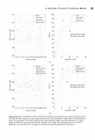
FIGURE 5.3.4.3.3 Comparison of Le , FDTD, 3D ray tracing, and angle formula models. (a) Data points
e
of FDTD, 3D ray tracing, Lee mod l , a n gle formula, and measured data of same floor. (b) Data points of
FDTD, 3D ray tracing, Lee model, n gle formula, and measured data of one-floor difference. (c) Data
a
e
points of FDTD, 3D ray tracing, Lee model, angle formula mod l , and measured data of a two-floor
a
j
difference. (A color version of this figure is av i l able at www.mhprofessional.com i wpm.)