
Page 335 - Integrated Wireless Propagation Models
P. 335
I n - B u i l d i n g ( P i c o c e l l ) P r e d i c t i o n M o d e l s 313
where j = 1 is when the receiver is moving on the separated floor and measuring at
the diffraction area and j = 2 is measuring at the nondiffraction area. The three compo
nents are
(5.3.2.2.2.1)
L" = m 12 · • log [n ] + A in dB (5.3.2.2.2.5)
;1
N
0
1 Ln (d) = L(d ) + m log d (for diffraction area) (5.3.2.2.2.10)
1 ,
0
2 Ln (d) = L(d ) + m log d (for nondiffraction area) (5.3.2.2.2.11)
2 ,
The detailed description of Eq. (5.3.2.2.2.12) has been shown in Sec. 5.3.2.2.2.
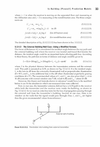
5.3.4.3 The External Building Wall Case-Using a Modified Formula
The focus of Reference 41 is considered the incident angle between the ray path and
the external building wall where the receiver was located and found that besides the
distance, the incident angle could be an important factor affecting path loss. According
to their theory, the path loss in terms of distance and angle could be given by
L = 32.4+ 20log(f cH J + 20log(S)+ L, + L c, (1- s in 9 ) 2 (in dB) (5.3.4.3.1)
where S is the physical distance between the transmission antenna and the external
3
wall. This path is assumed as LOS, as shown in Fig. 5.3.4. . 1 . e is the incident angle,
L, is the loss in dB from the externally illuminated wall at perpendicular illumination
(8 = 90°), and L is the additional loss in the dB when illuminated at perfectly grazing
c,
conditions (9 = 0°). The recommended values of L , and L are also given that L , = 4 to
c,
10 dB (concrete with normal window size 7 dB, wood 4 dB) and Lee = about 20 dB.
However, this theory and formula shown in reference9 would have to be modified
before it can fit the situation in which our measured data were collected.
First, in our case, the transmitter antenna did not have a LOS path to the receiver
while both the transmitter and the receiver were inside the building, as shown in
Fig. 5.3.4.3.2. So we need an extra loss term for the loss of propagation passing through
the external wall from the transmitter's building. Second, in our case, there is no
window on the walls that the signal would pass through; thus, L , and L are higher
c,
than the given recommended values from reference.9
FIGURE 5.3.4.3.1 Penetration i n to building from external transmitter.