
Page 351 - Integrated Wireless Propagation Models
P. 351
I n - B u i l d i n g ( P i c o c e l l ) P r e d i c t i o n M o d e l s 329
Source ray
Reception I
� o ·
bject 5
I \
T1 R1
Reception / \ Reception
�
Object 9 Object 1 �
1
\ / \
T2 R3
I \
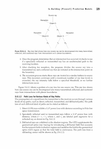
FIGURE 5.6.1.1 Ray tree that shows how one source ray can be decomposed into many transmitted,
reflected, and scattered rays from n tersections with planar boundaries.
i
4. Once the program determines that an intersection has occurred, it checks to see
if a specularly reflected or transmitted ray has an unobstructed path to the
receiving location.
5. After checking for reception, the program divides the source ray into a
transmitted ray and a reflected ray that are initiated at the intersection point on
the boundary.
6. The recursion process starts; these rays are treated in a similar fashion to source
rays. This recursion continues until a maximum number of ray tree levels is
exceeded, the ray intensity falls below a specified threshold, or no further
intersections occur.
Figure 5.6 1 . 1 shows a portion of a ray tree for one source ray. This ray tree shows
.
how one source ray can be decomposed into many transmitted, reflected, and scattered
rays from intersections with planar boundaries
5.6. 1.2 Path Loss for Various Kinds of Ray Paths
The propagation of a signal from the transmitter to the receiver occurs through various
kinds of ray paths, such as direct, reflected, transmitted, and diffracted paths. The path
loss of each different kind of paths can be stated as follows:
2
1. Direct (LOS) rays exhibit a 1 I d power loss with distance according to Friis free
space transmission.
2
2. Specularly reflected and/ or transmitted rays follow a 1 I d power loss with
distance, where d = r1 + r2 where r1 and r2 are labeled path segments for a
reflected ray, as shown in Fig. 5.6.1.2.
3. Diffracted rays are exhibited in the shadow regions. The GTD supplements the
geometrical optics (ray tracing) by introducing a diffracted field that accounts
for the nonzero fields in shadow regions and modifies the field in the geometrical
optics (GO) region so that the total field is continuous. The path loss from a
diffracting corner will be shown in Eq. (5.6.1.1).