Page 349 - Integrated Wireless Propagation Models
P. 349

I n - B u i l d i n g   ( P i c o c e l l )   P r e d i c t i o n   M  o d e l s    327

                             80
                                                                          .
                                                                      !
                             70      .      .   ·  ·   -  ··-  .  · · · · · · ···· ····  ·  -  ···········  ..  .. ... .
                                                                      .
                                                                      , .
                                  ·
                                  .
                                :  l  ::�: ::r   :  : r  ·     r
                                            _
                             60
                          in
                          "0
                          --;  50   · · · · · · ··!· · · · · · ·· .. · ··· · · ··:·· ··· ·· ·   ..   . . . ... ...... . .. .  .. .. . .... ..... . . :i, ·· · · ·· · ··· · ··· · ·
                           (/)
                          _Q                                          . _
                           0                      .  .... .... ..... ;-·--............ ! ................. !' ............. ..
                                             .
                                                   .
                                                                      .
                                             .
                           0   40   ................ r · · · ·   ....   ··· t ........ .... . r . .  :   �
                          u:::              :
                                                                .
                                      .
                                                          .
                                     .. , ................ 1" ..... ..... ............ ... i ........... 1 ................ ;···-.......... .
                                                .
                                             ...
                             30   ............           .     ·
                                                  I
                             20   ··· · · ·· · · · · ····!· · ···· · · · ·· ····· ·�· · ············· ·� · ····· ······ · ···� ······ · ·  ·  · · · · · · ··!··· · · ··· ···· ··· ··!··· ··· · · ·· · · · · · ·
                                     l      l            I     �      1
                             1 0
                               1     2     3    4     5    6
                                                N u mber of floors
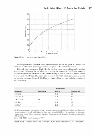
               FIGURE 5.5.2.1  Loss versus number of floors.
                  Typical parameters, based on various measurement results, are given in Tables 5.5.2.1
               and 5.5.2.2. Additional general guidelines are given at the end of the section.
                  The path-loss exponent is 20 dB/ dec for the free space loss and is usually applied
               to open area. However, the path-loss exponent can be lower than 20 dB/ dec based on
               the measurement results because the corridors might actually cause a tunnel effect.
               It is around 18 dB/ dec. The path-loss exponent for wall penetration and  around
               corners  is  between  30  and  40  dB/ dec,  depending  on  the  building  material
               and structure.

                                                          Environment
                Frequency               Residential      Office          Commercial
                    M
                900  H z                                 3.3             2.0
                1.2-1.3 GHz                              3.2             2 . 2
                1.8-2 .0 GHz           2.8               3.0             2 . 2
                4.0 GHz                                  2.8             2 . 2
                60 GHz*                                  2 . 2           1 . 7


               *60 GHz values assume propagation within a single room  r   space, and  o d    not include any allowance
                                                        o
                for  transmission through walls.  Gaseous  absorption around  60  GHz  is  also  significant  for  distances
                greater  than  about  100  m  which  may  influence  frequency  re-use  distances.  (See  Recommendation
                ITU -R P.676.)
               Source: Table  5.5.2.1 from/7 courtesy of ITU.
               TABLE 5.5.2.1  Distance Power Loss Coefficients, N, for I n door Transmission Loss Calculation
   344   345   346   347   348   349   350   351   352   353   354