
Page 352 - Integrated Wireless Propagation Models
P. 352
330 C h a p t e r F i v e
Wall
Receiver
Wall
d
d
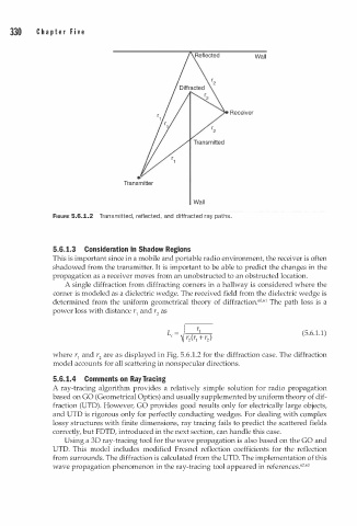
FIGURE 5.6.1.2 Transmitte , reflected, and i ffracted ray paths.
5.6. 1.3 Consideration in Shadow Regions
This is important since in a mobile and portable radio environment, the receiver is often
shadowed from the transmitter. It is important to be able to predict the changes in the
propagation as a receiver moves from an unobstructed to an obstructed location.
A single diffraction from diffracting corners in a hallway is considered where the
corner is modeled as a dielectric wedge. The received field from the dielectric wedge is
0 1
determined from the uniform geometrical theory of diffraction.6 •6 The path loss is a
power loss with distance r and r as
1
2
(5.6.1.1)
where r and r are as displayed in Fig. 5.6.1.2 for the diffraction case. The diffraction
1
2
model accounts for all scattering in nonspecular directions.
5.6. 1.4 Comments on Ray Tracing
A ray-tracing algorithm provides a relatively simple solution for radio propagation
based on GO (Geometrical Optics) and usually supplemented by uniform theory of dif
fraction (UTD). However, GO provides good results only for electrically large objects,
and UTD is rigorous only for perfectly conducting wedges. For dealing with complex
lossy structures with finite dimensions, ray tracing fails to predict the scattered fields
correctly, but FDTD, introduced in the next section, can handle this case.
Using a 30 ray-tracing tool for the wave propagation is also based on the GO and
UTD. This model includes modified Fresnel reflection coefficients for the reflection
from surrounds. The diffraction is calculated from the UTD. The implementation of this
2
wave propagation phenomenon in the ray-tracing tool appeared in references.6 •63