
Page 368 - Integrated Wireless Propagation Models
P. 368
346 C h a p t e r S i x
I
6.3. 2 Design Parameters and n put Data
6.3.2. 1 Design Parameters
The following design parameters are used as a default set in the prediction model to
design a system in a special area:
Transmitter height: 30 to 40 m
Antenna gain: 17 dBi
Output power: 13.5 W
Cable loss: 2 to 3 dB
Vertical beamwidth: 4° to 5°
The antenna pattern used in the model is shown later in Fig. 6.3.3.2.1. The coverage
plot was generated based on a 144-dB link budget. This translates to a receiver level
about -85 dBm forward link coverage. This value is reasonable for providing ground
car coverage. USGS terrain (a 3 x 3-sec map) data were used for this study.
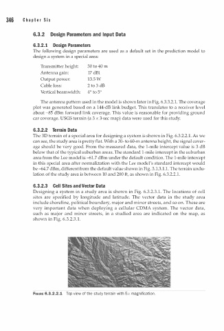
6.3.2.2 Terrain Data
The 3D terrain of a special area for designing a system is shown in Fig. 6.3.2.2.1. As we
can see, the study area is pretty flat. With a 30- to 60-m antenna height, the signal cover
age should be very good. From the measured data, the 1-mile intercept value is 3 dB
below that of the typical suburban areas. The standard 1-mile intercept in the suburban
area from the Lee model is -61.7 dBm under the default condition. The 1-mile intercept
in this special area after normalization with the Lee model's standard intercept would
be -64.7 dBm, different from the default value shown in Fig. 3.1.3. . 1 . The terrain undu
1
lation of the study area is between 10 and 200 ft, as shown in Fig. 6.3.2.2. .
1
a
6.3.2.3 Cell Sites n d Vector Data
3
Designing a system in a study area is shown in Fig. 6.3.2. . 1 . The locations of cell
sites are specified by longitude and latitude. The vector data in the study area
include shoreline, political boundary, major and minor streets, and so on. These are
very important data when deploying a cellular CDMA system. The vector data,
such as major and minor streets, in a studied area are indicated on the map, as
shown in Fig. 6.3.2. . 1 .
3
FIGURE 6.3.2.2.1 Top view of the study terr i n with x magnification.
a
5