
Page 374 - Integrated Wireless Propagation Models
P. 374
352 C h a p t e r S i x
6.3.5 System Design in Special Areas with New Technologies
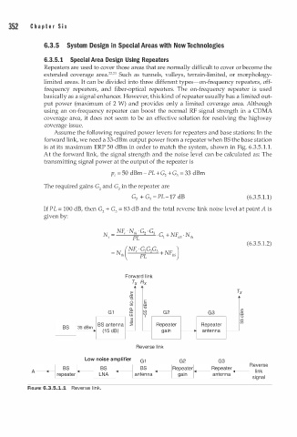
6.3.5. 1 Special Area Design Using Repeaters
Repeaters are used to cover those areas that are normally difficult to cover or become the
222
extended coverage area. · 3 Such as tunnels, valleys, terrain-limited, or morphology
limited areas. It can be divided into three different types-on-frequency repeaters, off
frequency repeaters, and fiber-optical repeaters. The on-frequency repeater is used
basically as a signal enhancer. However, this kind of repeater usually has a limited out
put power (maximum of 2 W) and provides only a limited coverage area. Although
using an on-frequency repeater can boost the normal RF signal strength in a COMA
coverage area, it does not seem to be an effective solution for resolving the highway
coverage issue.
Assume the following required power levers for repeaters and base stations: In the
forward link, we need a 33-dBm output power from a repeater when BS the base station
5
is at its maximum ERP 50 dBm in order to match the system, shown in Fig. 6.3. . 1 . 1 .
A t the forward link, the signal strength and the noise level can e calculated as: The
b
transmitting signal power at the output of the repeater is
p1 = 50 dBm- PL + G + G = 33 dBm
2
3
The required gains G and G in the repeater are
2
3
G + G = PL- 1 7 dB (6.3.5.1.1)
2
3
If PL = 100 dB, then G + G = 83 dB and the total reverse link noise level at point A is
2
3
given by:
NF, ·No, ·G · G
N = 2 3 G NF · N
· 1 +
t PL BS th
.
(6.3.5 1 . 2)
Forward link
Tx Rx
•
E
aJ
"0
0 E
I!) aJ
0.. "0
E
G 1 a: I!) G2 G3 aJ
w '? "0
('")
lo:- '" ' _.0� BS antenna � Repeater Repeater ('")
� ., (1 5 dB) r-- gain antenna
Reverse link
Low noise amplifier G1 G2 G3
Reverse
A - ---GD I an:�na r -- link
'------''---------" signal
l
FIGURE 6.3.5.1.1 Reverse i n k.