
Page 379 - Integrated Wireless Propagation Models
P. 379
T h e l e e C o m p r e h e n s i v e M o d e l - I n t e g r a t i o n o f t h e T h r e e l e e M o d e l s 357
• >= -7 dB
>= -9 dB
>= -11 dB
>= -13 dB
>= -15 dB
>= -17 dB
FIGURE 6.3.5.3.3 Special-area CDMA EJio plot with repeaters. (A color version of this figure is
available at www.mhprofessiona . c omjiwpm.)
l
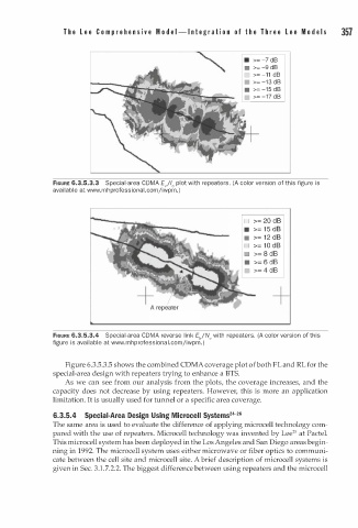
D >= 20 dB
• >= 1 5 dB
• >= 1 2 dB
D >= 1 0 dB
•
FIGURE 6.3.5.3.4 Special-area CDMA reverse link E"/N0 with repeaters. (A color version of this
a
figure is available at www.mhprofession l . c omjiwpm. )
o
F
Figure 6.3.5.3.5 shows the combined CDMA coverage plot f both L and RL for the
special-area design with repeaters trying to enhance a BTS.
As we can see from our analysis from the plots, the coverage increases, and the
capacity does not decrease by using repeaters. However, this is more an application
limitation. It is usually used for tunnel or a specific area coverage.
6.3.5.4 Special-Area Design Using Microcell Systems24-26
The same area is used to evaluate the difference of applying microcell technology com
2
pared with the use of repeaters. Microcell technology was invented by Lee 5 at Pactel.
This microcell system has been deployed in the Los Angeles and San Diego areas begin
ning in 1992. The microcell system uses either microwave or fiber optics to communi
cate between the cell site and microcell site. A brief description of microcell systems is
given in Sec. 3.1.7.2.2. The biggest difference between using repeaters and the microcell