
Page 375 - Integrated Wireless Propagation Models
P. 375
T h e l e e C o m p r e h e n s i v e M o d e l - I n t e g r a t i o n o f t h e T h r e e l e e M o d e l s 353
where NF, is the repeater noise figure of the receiver, NFbs is the base station noise
figure, and N11, is the thermal noise level. The description of noise figure appeared
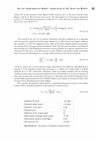
in Sec. 6.5.3. Using the parameters in Table 6.3.5. . 1 , the dB value of total noise from
1
.
Eq. (6.3.5 1 .2) at point A is
[ (63 X 31.6 )]
·
N1 = 10 log N1, + 6.3 = 10 log(N111 1 0.27)
50. 1
1
(6.3.5.1.3)
= N111 + 10.1 dB (dB)
This result of Eq. (6.3.5.1.3) clearly illustrates that the installation of a repeater
will increase the noise level of the base station by 2.1 dB, as the noise figure without
the repeater is 8 dB. The signal-to-noise ratio of the base stations and consequently
the reverse link coverage will be decreased. Note that the forward link is not affected
by the result in a link imbalance from the existing system. In a typical suburban envi
ronment (35 dB/dec), a 2.1-dB increase in base station noise level can be translated
into a 13 percent shrinkage in coverage radius at the reverse link as follows:
( R )35 R
R
R: = 2.1 dB => � = 0.87 (6.3.5.1.4)
where R1 and R2 are reverse link coverage radii before and after the installation of a
repeater. If the original reverse link coverage is a radius of 5 miles, then it will be
reduced to 5 x 0. 87 = 4.36 miles. Therefore, when we install repeaters into an existing
wireless system, they should not be placed at the cell boundary. A 13 percent margin is
necessary to keep the reverse link coverage in a suburban area. When designing a new
system with repeaters, the increase of base station noise figures is always be taken into
account when determining the link budget.
The cascade of repeaters will introduce a significant increase in noise level. A base
station with n cascaded repeaters will represent a noise level of
.
(6.3.5 1 .5)
Repeater RF n put -55 dBm
i
Repeater power output -33 dBm
Repeater noise figure 8 dB
Repeater gai n G
2
Repeater donor antenna gai n G3
Base-station coverage antenna gai n 15 dB
Base-station receiver noise figure 8 d B
BS maximum erp 50 B m
d
TABLE 6-3.5.1.1 Parameters of Repeater and Base Station