
Page 85 - Integrated Wireless Propagation Models
P. 85
M a c r o c e l l P r e d i c t i o n M o d e l s - P a r t 1 : A r e a - t o - A r e a M o d e l s 63
Profi le evaluation
D I F
BLOS:
TRO
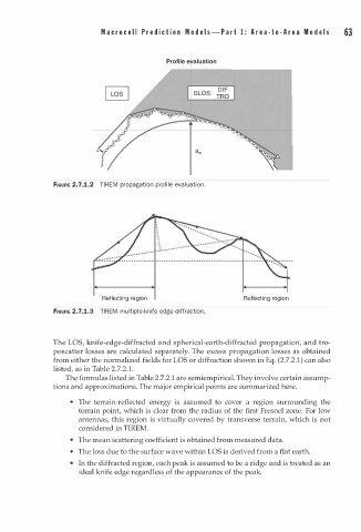
FIGURE 2.7.1.2 TIREM propagation profile ev l uation.
a
Reflecting region Reflecting region
m
FIGURE 2.7.1.3 TIREM u l tiple-knife edge diffraction.
The LOS, knife-edge-diffracted and spherical-earth-diffracted propagation, and tro
poscatter losses are calculated separately. The excess propagation losses as obtained
from either the normalized fields for LOS or diffraction shown in Eq. (2.7.2.1) can also
1
listed, as in Table 2.7.2. .
The formulas listed in Table 2.7.2.1 are semiempirical. They involve certain assump
tions and approximations. The major empirical points are summarized here.
• The terrain-reflected energy is assumed to cover a region surrounding the
terrain point, which is clear from the radius of the first Fresnel zone. For low
antennas, this region is virtually covered by transverse terrain, which is not
considered in TIREM.
• The mean scattering coefficient is obtained from measured data.
• The loss due to the surface wave within LOS is derived from a flat earth.
• In the diffracted region, each peak is assumed to be a ridge and is treated as an
ideal knife edge regardless of the appearance of the peak.