
Page 81 - Integrated Wireless Propagation Models
P. 81
M a c r o c e I P r e d i c t i o n M o d e I s - P a r t 1 : A r e a - t o - A r e a M o d e I s 59
I
-20 .----------,.----------,-----------,
-40
-60
iil
:s.
(/)
Sl -100
.r:
8! -120
-140
-160
-180 �--------�--------�----------�
1 0 1 1 0 2 1 0 3 1 0 4
Distance (m)
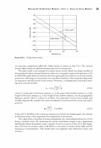
FIGURE 2.5.1 Clutter factor mode . l
a
1
an extra loss component called the clutter factor, s shown in Fig. 2.5. . The various
models differ based on different frequencies and environments.
The Egli model6 is an example of a clutter factor model. Based on a large number of
measurements taken around American cities over irregular terrain at frequencies of 90
to 1000 MHz, Egli observed, besides that the signal path loss follows an inverse fourth
power law with range, an excess loss over and above that loss. This excess loss depended
on frequency and the nature of the terrain. Therefore, a multiplicative factor � is intro
duced to account for this:
(2.5.2)
where Gb is the gain of the base antenna, G., is the gain of the mobile antenna, hb is the
height of the base antenna, h., is the height of the mobile antenna, d is the propagation
2
/
distance, and � = ( 40 I ) , where f is in MHz. The subscripts b and m refer to base and
mobile, respectively, and � is the factor introduced to account for the excess loss and is
given by
(40] 2
� - f M Hz (2.5.3)
in
- y
In Eq. (2.5.3), 40 MHz is the reference frequency at which the median path loss reduces
to the plane earth value regardless the irregularity of the terrain.
The value of � is a function of terrain irregularity, the value obtained from Eq. (2.5.3)
being a median value. By assuming the terrain undulation height to be a lognormal
distribution about its median value, a family of curves is given in Fig. 2.5.2. The depar
ture of � from its median value at 40 MHz is a function of terrain factor (dB) and the
frequency of transmission. This model does not explicitly take diffraction losses into
account.