
Page 83 - Integrated Wireless Propagation Models
P. 83
M a c r o c e l l P r e d i c t i o n M o d e l s - P a r t 1 : A r e a - t o - A r e a M o d e l s 61
R T R
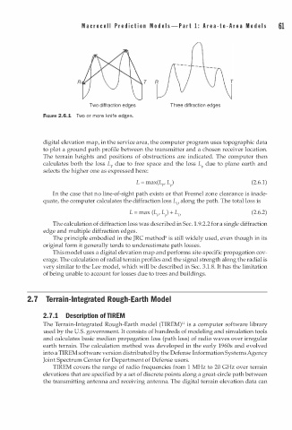
Two diffraction edges Three diffraction edges
FIGURE 2.6.1 Two or more knife edges.
digital elevation map, in the service area, the computer program uses topographic data
to plot a ground path profile between the transmitter and a chosen receiver location.
The terrain heights and positions of obstructions are indicated. The computer then
calculates both the loss L due to free space and the loss L due to plane earth and
F
P
selects the higher one as expressed here:
(2.6.1)
In the case that no line-of-sight path exists or that Fresnel zone clearance is inade
quate, the computer calculates the diffraction loss L0 along the path. The total loss is
(2.6.2)
1
The calculation of diffraction loss was described in Sec. . 9.2.2 for a single diffraction
edge and multiple diffraction edges.
The principle embodied in the JRC method8 is still widely used, even though in its
original form it generally tends to underestimate path losses.
This model uses a digital elevation map and performs site-specific propagation cov
erage. The calculation of radial terrain profiles and the signal strength along the radial is
very similar to the Lee model, which will be described in Sec. 3.1.8. It has the limitation
of being unable to account for losses due to trees and buildings.
a
2. 7 Terr i n - I n tegrated Rough-E r th Model
a
2 . 7 . 1 Description of TIREM
11
The Terrain-Integrated Rough-Earth model (TIREM) is a computer software library
used by the U.S. government. It consists of hundreds of modeling and simulation tools
and calculates basic median propagation loss (path loss) of radio waves over irregular
earth terrain. The calculation method was developed in the early 1960s and evolved
into a TIREM software version distributed by the Defense Information Systems Agency
Joint Spectrum Center for Department of Defense users.
TIREM covers the range of radio frequencies from 1 MHz to 20 GHz over terrain
elevations that are specified by a set of discrete points along a great-circle path between
the transmitting antenna and receiving antenna. The digital terrain elevation data can