
Page 82 - Integrated Wireless Propagation Models
P. 82
60 C h a p t e r T w o
+20
+ 1 5
+ 1 0
+5
co 40
""0 0 Median-50
c5 60
ti
$ -5 70
c 80
-� -10
� 90
-15
-20
-25
-30
40 50 60 80 1 0 0 1 5 0 200 300 500 1 0 00
Frequency (MHz)
a
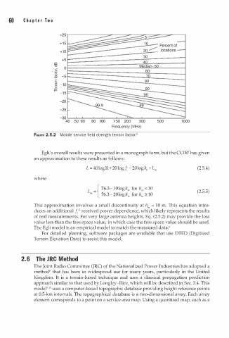
FIGURE 2.5.2 Mobile service field strength terr i n factor.6
Egli's overall results were presented in a monograph form, but the CCIR7 has given
an approximation to these results as follows:
L = 40logR + 20logf -20loghb + L"' (2.5.4)
c
where
-{ 76.3- 1 0 l ogh"' for h"' < 10
L "' - (2.5.5)
�
76.3- 2 0 l ogh"' for h"' 1 0
This approximation involves a small discontinuity at h"' = 10 m. This equation intro
z
duces an additional f e - received power dependence, which likely represents the results
of real measurements. For very large antenna heights, Eq. (2.5.2) may provide the loss
value less than the free space value, in which case the free space value should be used.
The Egli model is an empirical model to match the measured data.6
For detailed planning, software packages are available that use DTED (Digitized
Terrain Elevation Data) to assist this model.
2.6 The R C M e thod
J
The Joint Radio Committee (JRC) of the Nationalized Power Industries has adopted a
method8 that has been in widespread use for many years, particularly in the United
Kingdom. It is a terrain-based technique and uses a classical propagation prediction
approach similar to that used by Langley-Rice, which will be described in Sec. 3.4. This
10
model9• uses a computer-based topographic database providing height reference points
at 0.5-km intervals. The topographical database is a two-dimensional array. Each array
element corresponds to a point on a service area map. Using a quantized map, such as a