Page 78 - Integrated Wireless Propagation Models
P. 78

56    C h a p t e r   T w o


                                               ,  ,
                               ...               '  ,  ,
                                ... ,
                        "0   60                       ,,
                        .l!l                              � ....
                         ctl       .... ...  '           ,,f
                                                             ' ... ,
                        '5            '  '            Free space  ',,
                         �
                        :I:'                                          ,  ,
                         ctl          '�' ... ,   '                     ... ... ,
                                         · ,
                         s:  40
                        _Q                     '
                        :.;;::                    '
                         Cll               � "'� ,  Plane earth
                         c
                         0               /            ,  /
                        .E   20  - Knife-edge   .  ,,   '  '   ...
                        2        diffra  tion theory   '\,   '
                         Cll                     · �         '   '
                         E
                         Cii                         '� '\      .......... ...
                         Cl.                                       ',
                             0
                        0
                         >                                            .... ... ,
                                                      \
                                                           .
                         e              -�            ' ·   � \          ... ,
                         (.)
                        .E
                                      -
                                       -
                                        -
                         Cll      � "' -�              \  �
                                             -
                                          -- -
                         c   -20
                         0
                         Cll                             \     \-.
                         >
                         0
                        .0
                         ctl
                        Ill                               \  \""'
                        "0   -40
                                         Smooth earth theory
                                              I  K = 4/3� K = 5..:.  I\.
                              1 0    20       50    1 0 0   200     500    1 0 00
                                                    Miles
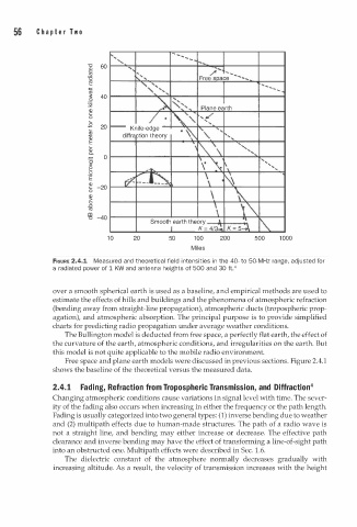
               FIGURE 2.4.1  Measured and theoretical field  n tensities in the 40- to 50-MHz range, adjusted for
                                                 i
               a radiated power of 1  KW and antenna heights of 500 and 30 ft.4
               over a smooth spherical earth is used as a baseline, and empirical methods are used to
               estimate the effects of hills and buildings and the phenomena of atmospheric refraction
               (bending away from straight-line propagation), atmospheric ducts (tropospheric prop­
               agation), and atmospheric absorption. The principal purpose is to provide simplified
               charts for predicting radio propagation under average weather conditions.
                  The Bullington model is deducted from free space, a perfectly flat earth, the effect of
               the curvature of the earth, atmospheric conditions, and irregularities on the earth. But
               this model is not quite applicable to the mobile radio environment.
                  Free space and plane earth models were discussed in previous sections. Figure 2.4.1
               shows the baseline of the theoretical versus the measured data.
               2.4.1  Fading, Refraction from Tropospheric Transmission, and  Diffraction4
               Changing atmospheric conditions cause variations in signal level with time. The sever­
               ity of the fading also occurs when increasing in either the frequency or the path length.
               Fading is usually categorized into two general types: (1) inverse bending due to weather
               and (2) multipath effects due to human-made structures. The path of a radio wave is
               not a straight line, and bending may either increase or decrease. The effective path
               clearance and inverse bending may have the effect of transforming a line-of-sight path
                                                                     1
               into an obstructed one. Multipath effects were described in Sec.  . 6.
                  The  dielectric  constant  of the  atmosphere  normally  decreases  gradually  with
               increasing altitude. As a result, the velocity of transmission increases with the height
   73   74   75   76   77   78   79   80   81   82   83