
Page 76 - Integrated Wireless Propagation Models
P. 76
54 C h a p t e r T w o
1 0 0 On a radial through
Dover
1 1 0
1 2 0 \ (
(/) 1 3 0 ;',��� Wf/,\\ II
� I'
Qi : �0�.\
..c 1 4 1,-,�i , :,\\ /I\
· g 0 '.' ' ' \\ :\ �I �
'
"0 " , I �c
c ' 10 "" � /
· ;;; 1 5 0 , u I �� / 450
�
'
(/)
_Q ' , ' :, \\ / ......... ......... / !-- -.......
'
� 1 6 0 '
' · - - ' -----
c.. 900 - - - - -
0 1 7 ' ' - - . '
Q) 0
::J
""iii 1 8
> 0
� 1 2 0
'6 On a radial through
Q) - New Rochelle
� 1 3 0 1---- '
, /
/
/ -�\ �G
1 4 0 � � "s a �
\ ' A '? - - .
'\ � / ..... \' � 0 � �� /
Q
\ -------;' r<, ..: --
1 5 0 � o \l --', . · , . /- ' - � , - I
I
/ � '/ � \ , I
\• "/ - - - -
1 6 0
8 1 0 1 2 1 4 1 6 1 8 20 22 24 26 28 30 32
Distance from transmitter in miles
a
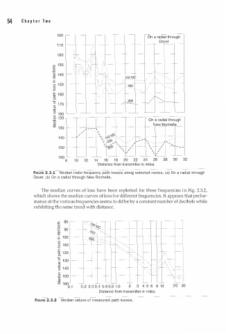
FIGURE 2.3.1 Median radio frequency path losses l ong selected routes. (a) On a radial through
Dover. (b) On a radial through New Rochelle.
The median curves of loss have been replotted for three frequencies in Fig. 2.3.2,
which shows the median curves of loss for different frequencies. It appears that perfor
mance at the various frequencies seems to differ by a constant number of decibels while
exhibiting the same trend with distance.
(/) 80 �I
Qi
..c il? c
Ti 90
Q) " ---1 s o fa:=
"0 I" �
-� 1 0 0 ._g - '()..
(/) _ g D - � - �
(/)
_Q 1 1 0 ,'-._ �
.r: '�-.... �
1il 1 2 0
c.. '
..
0 1 3 0 � \.._ � )\
..
Q)
::J .. . � v �;\
""iii 1 4 0 � /.
> / '\ 'o f--o--,
c ',:::- / \
� 1 5 0 8 ..0 ,
Q)
� 1 6 0
1
0
0 . 1 0 . 2 0.3 . 4 0 . 6 0.8 . 0 2 3 4 5 6 8 1 0 2 0 30
Distance from transmitter in miles
FIGURE 2.3.2 Median val u es of measured path losses.