
Page 79 - Integrated Wireless Propagation Models
P. 79
M a c r o c e l l P r e d i c t i o n M o d e l s - P a r t 1 : A r e a - t o - A r e a M o d e l s 57
above the ground. As the change in dielectric constant is linear with height, radio waves
continue to travel in a straight line over an earth whose radius is now
a
ka = a d £ (2.4.1)
1+
2dh
where a is true radius of earth and d£/ dh is the rate of change of dielectric constant with
height.
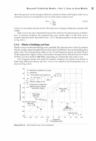
Radio waves are also transmitted around the earth by the phenomenon of diffrac
tion. At grazing incidence, the expected loss over a knife edge is 6 dB while over a
smooth, spherical earth, described in Sec. . 9 .2.2. The phenomenon can also been shown
1
.
in Fig. 2.4 1 . 1 .
2 . 4 . 2 Effects f Buildings n d Trees
a
o
Shadow losses result from buildings, trees, and hills. The data from New York City indicate
that the median signal strength (50 percent) is about 25 dB below the corresponding plane
earth value. The corresponding values for the 10 and 90 percent points are about 15 and
35 dB, respectively. Typical values of attenuation through a brick wall are from 2 to 5 dB at
30 MHz, and 10 to 40 dB at 3000 MHz, depending on whether the wall is dry or wet.
Over irregular terrain and under the shadow condition, the shadow loss based on
knife-edge diffraction theory (see Sec. 1 . 6) is to be added to the transmission loss, as
shown in Fig. 2.4.2.1.
30�--�----�----�--�----�----�--�----�--�----�
R = Reflection coefficient of surface
H = Clearance
20
H0 = First Fresnel zone clearance =
!!l_ [1+..JH2/H1 ]2 [ __ F l2/3
10 M = __
H } K..J3 2 4000
H
=
0 : A ntenna height in feet
Q) F = Frequency in megacycles
u
ctl
0. Effective Earth's Radius
(J) -10 K =
Q) True Earth's Radius -f-?--+--'-'--+-.
�
(J)
2 -30 1------+
·u
Q)
0
6
-70L- ---L�--� L_ __ L_ __ _L __ __ � __ __ L_ __ _L __ � � -L � -- L- �
-2.5 -2.0 -1.5 -1.0 -0.5 0 0.5 1.0 1.5 2.0 2.5
H Clearance
H0 First fresnel zone
FIGURE 2.4.1.1 Transmission loss versus clearance.