
Page 159 - Intro Predictive Maintenance
P. 159
150 An Introduction to Predictive Maintenance
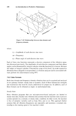
Figure 7–20 Relationship between time-domain and
frequency-domain.
where:
A x = Amplitude of each discrete sine wave
wt = Frequency
f x = Phase angle of each discrete sine wave
Each of these sine functions represents a discrete component of the vibration signa-
ture discussed previously. The amplitudes of each discrete component and their phase
angles can be determined by integral calculus when the function f(t) is known. Because
the subject of integral calculus is beyond the scope of this book, the math required to
determine these integrals is not presented. A vibration analyzer and its associated soft-
ware perform this determination using FFT.
7.6.2 Data Formats
Both time-domain and frequency-domain vibration data can be acquired and analyzed
in two primary formats: steady-state or dynamic. Each of these formats has strengths
and weaknesses that must be clearly understood for proper use. In addition, each of
these formats can be obtained as single- or multichannel data.
Steady-State
Most vibration programs that use microprocessor-based analyzers are limited to
steady-state data. Steady-state vibration data assumes that the machine-train or process
system operates in a constant, or steady-state, condition. In other words, the machine
is free of dynamic variables such as load, flow, and so on. This approach further
assumes that all vibration frequencies are repeatable and maintain a constant rela-
tionship to the rotating speed of the machine’s shaft.