
Page 205 - Introduction to Autonomous Mobile Robots
P. 205
190
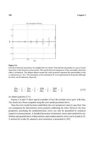
Figure 5.4 Chapter 5
Growth of the pose uncertainty for straight-line movement: Note that the uncertainty in y grows much
faster than in the direction of movement. This results from the integration of the uncertainty about the
robot’s orientation. The ellipses drawn around the robot positions represent the uncertainties in the
θ
x,y direction (e.g. 3σ ). The uncertainty of the orientation is not represented in the picture although
its effect can be indirectly observed.
∂ ∆s 1 ∂ ∆s 1 ∂ ∆θ 1 ∂ ∆θ 1
----------- = --- ; ---------- = --- ; ----------- = --- ; ---------- = – --- (5.15)
∂ ∆s 2 ∂ ∆s 2 ∂ ∆s b ∂ ∆s b
r l r l
we obtain equation (5.11).
Figures 5.4 and 5.5 show typical examples of how the position errors grow with time.
The results have been computed using the error model presented above.
Once the error model has been established, the error parameters must be specified. One
can compensate for deterministic errors properly calibrating the robot. However the error
parameters specifying the nondeterministic errors can only be quantified by statistical
(repetitive) measurements. A detailed discussion of odometric errors and a method for cal-
ibration and quantification of deterministic and nondeterministic errors can be found in [5].
A method for on-the-fly odometry error estimation is presented in [105].