Page 121 - Introduction to Computational Fluid Dynamics
P. 121

P1: IWV
                                                                                                11:7
                                                                                   May 25, 2005
                           CB908/Date
            0521853265c04
                     100
                             50         0 521 85326 5                          2D BOUNDARY LAYERS
                             40
                                                                 Re = 500   Pr = 0.7


                             30
                                    f ∗ Re
                                                                    (Uc / Ubar) ∗ 10

                             20


                                O
                             10  O
                                           Previous Num Soln            Nu x
                                  O
                                   O
                                        O
                                                    O
                              0
                             0.000      0.025     0.050     0.075   +  0.100     0.125     0.150
                                                                   X
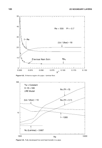
                            Figure 4.8. Entrance region of a pipe – laminar flow.


                            100
                                    Tw = Constant
                                    X / D = 100
                                                                      Nu (Pr = 5)
                                    LRE Model


                                    (Uc / Ubar) ∗ 10                  Nu (Pr = 0.7)


                             10

                                                                      f ∗ 1000


                                    Nu (Laminar) = 3.667

                              1000                                                         10000
                                                                Re
                            Figure 4.9. Fully developed flow and heat transfer in a pipe.
   116   117   118   119   120   121   122   123   124   125   126