
Page 220 - Introduction to Computational Fluid Dynamics
P. 220
P1: IWV
0 521 85326 5
CB908/Date
0521853265c06
6.4 APPLICATIONS
SECONDARY AIR DILUTION AIR May 25, 2005 11:10 199
CHAMBER WALL
PRIMARY E
ZONE X R = 0.0625 m
I
PREMIXED
FUEL T
+ SYMMETRY
AIR
L = 0.25 m
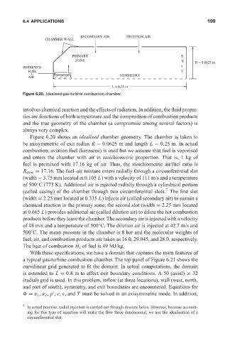
Figure 6.20. Idealised gas-turbine combustion chamber.
involves chemical reaction and the effects of radiation. In addition, the fluid proper-
ties are functions of both temperature and the composition of combustion products
and the true geometry of the chamber (a compromise among several factors) is
always very complex.
Figure 6.20 shows an idealised chamber geometry. The chamber is taken to
be axisymmetric of exit radius R = 0.0625 m and length L = 0.25 m. In actual
combustion, aviation fuel (kerosene) is used but we assume that fuel is vaporised
and enters the chamber with air in stoichiometric proportion. That is, 1 kg of
fuel is premixed with 17.16 kg of air. Thus, the stoichiometric air/fuel ratio is
R stoic = 17.16. The fuel–air mixture enters radially through a circumferential slot
(width = 3.75 mm located at 0.105 L) with a velocity of 111 m/s and a temperature
of 500 C (773 K). Additional air is injected radially through a cylindrical portion
◦
7
(called casing) of the chamber through two circumferential slots. The first slot
(width = 2.25 mm located at 0.335 L) injects air (called secondary air) to sustain a
chemical reaction in the primary zone; the second slot (width = 2.25 mm located
at 0.665 L) provides additional air (called dilution air) to dilute the hot combustion
products before they leave the chamber. The secondary air is injected with a velocity
of 48 m/s and a temperature of 500 C. The dilution air is injected at 42.7 m/s and
◦
◦
500 C. The mean pressure in the chamber is 8 bar and the molecular weights of
fuel, air, and combustion products are taken as 16.0, 29.045, and 28.0, respectively.
The heat of combustion H c of fuel is 49 MJ/kg.
With these specifications, we have a domain that captures the main features of
a typical gas-turbine combustion chamber. The top panel of Figure 6.21 shows the
curvilinear grid generated to fit the domain. In actual computations, the domain
is extended to L = 0.8 m to effect exit boundary conditions. A 50 (axial) × 32
(radial) grid is used. In this problem, inflow (at three locations), wall (west, north,
and part of south), symmetry, and exit boundaries are encountered. Equations for
= u 1 , u 2 , p , e, , and T must be solved in an axisymmetric mode. In addition,
7 In actual practise, radial injection is carried out through discrete holes. However, because account-
ing for this type of injection will make the flow three dimensional, we use the idealisation of a
circumferential slot.