
Page 221 - Introduction to Computational Fluid Dynamics
P. 221
P1: IWV
CB908/Date
0 521 85326 5
0521853265c06
200
2D CONVECTION – COMPLEX DOMAINS
GRID May 25, 2005 11:10
VECTOR PLOT
TURBULENT VISCOSITY
0.6
0.3
0.5
0.1
0.9
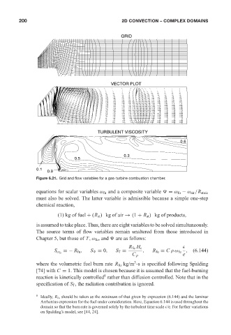
Figure 6.21. Grid and flow variables for a gas-turbine combustion chamber.
equations for scalar variables ω fu and a composite variable = ω fu − ω air /R stoic
must also be solved. The latter variable is admissible because a simple one-step
chemical reaction,
(1) kg of fuel + (R st ) kgofair → (1 + R st ) kg of products,
is assumed to take place. Thus, there are eight variables to be solved simultaneously.
The source terms of flow variables remain unaltered from those introduced in
Chapter 5, but those of T,ω fu , and are as follows:
R fu H c
=− R fu , S = 0, S T = , R fu = C ρω fu , (6.144)
S ω fu
C p e
3
where the volumetric fuel burn rate R fu kg/m -s is specified following Spalding
[74] with C = 1. This model is chosen because it is assumed that the fuel-burning
8
reaction is kinetically controlled rather than diffusion controlled. Note that in the
specification of S T , the radiation contribution is ignored.
8 Ideally, R fu should be taken as the minimum of that given by expression (6.144) and the laminar
Arrhenius expression for the fuel under consideration. Here, Equation 6.144 is used throughout the
domain so that the burn rate is governed solely by the turbulent time scale /e. For further variations
on Spalding’s model, see [44, 24].