
Page 234 - Introduction to Computational Fluid Dynamics
P. 234
P1: IWV
11:10
CB908/Date
0521853265c06
213
EXERCISES
a 0 521 85326 5 May 25, 2005 Symmetry Plane
b r
Φ Φ
X 2
4a
Symmetry Plane
a) MOON SHAPED DUCT X 1 b) CORDOID DUCT
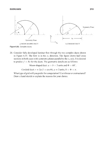
Figure 6.35. Complex ducts.
20. Consider fully developed laminar flow through the two complex ducts shown
in Figure 6.35. The flow is in the x 3 direction. The figure shows half cross
sections in both cases with symmetry planes parallel to the x 1 axis. It is desired
to predict f × Re for the ducts. The geometric details are as follows:
◦
Moon-shaped duct: a = b = 3 units and = 60 ,
Cordoid duct: r = 2a (1 + cos ), a = 2 units, 0 < <π.
What type of grid will you prefer for computation? Curvilinear or unstructured?
Draw a hand sketch to explain the reasons for your choice.