Page 229 - Introduction to Computational Fluid Dynamics
P. 229

P1: IWV
                                                                                   May 25, 2005
                           CB908/Date
                                                                                                11:10
            0521853265c06
                     208
                                        b 0 521 85326 5         2D CONVECTION – COMPLEX DOMAINS
                                                                  b                       e
                                                                                  f
                                                           c
                                       c
                                                                            a                      d
                                                        a
                            d

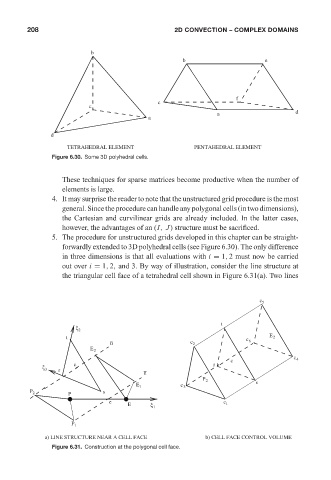
                                 TETRAHEDRAL ELEMENT                  PENTAHEDRAL ELEMENT
                            Figure 6.30. Some 3D polyhedral cells.


                               These techniques for sparse matrices become productive when the number of
                               elements is large.
                            4. It may surprise the reader to note that the unstructured grid procedure is the most
                               general. Since the procedure can handle any polygonal cells (in two dimensions),
                               the Cartesian and curvilinear grids are already included. In the latter cases,
                               however, the advantages of an (I, J) structure must be sacrificed.
                            5. The procedure for unstructured grids developed in this chapter can be straight-
                               forwardly extended to 3D polyhedral cells (see Figure 6.30). The only difference
                               in three dimensions is that all evaluations with i = 1, 2 must now be carried
                               out over i = 1, 2, and 3. By way of illustration, consider the line structure at
                               the triangular cell face of a tetrahedral cell shown in Figure 6.31(a). Two lines


                                                                                         c 5


                                                                             t
                                   ξ 2
                                t                                                    c 6    E 2
                                             n                       c 2
                                       E 2
                                                                                c                  c 4
                                   c                                       r
                         ξ 3
                              r
                                                       n
                                                                        P 2
                                                                                        s
                                                     E 1          c 3
                      P 2                  s
                                 P
                                             e                                c 1
                                                  E      ξ 1
                                  P 1
                          a) LINE STRUCTURE NEAR A CELL FACE             b) CELL FACE CONTROL VOLUME
                            Figure 6.31. Construction at the polygonal cell face.
   224   225   226   227   228   229   230   231   232   233   234