Page 227 - Introduction to Computational Fluid Dynamics
P. 227

P1: IWV
                                                                                   May 25, 2005
                                                                                                11:10
                           CB908/Date
            0521853265c06
                     206
                                                                2.0
                            2.02.0      0 521 85326 5           2D CONVECTION – COMPLEX DOMAINS
                                   WALL                               CENTER LINE
                                   WALL
                            1.61.6                              1.6
                                                                                       Mach No
                                                   Mach No
                            1.2                  Mach No        1.2
                             .2
                                  P/P
                                 P / Po                               P/P o
                                      O
                            0.88                                0.8
                            0
                             .
                                                                                     Expt Data
                                                 Expt Data
                                                 Expt Data
                             .
                            0.44                                0.4
                            0

                            0
                             .
                            0.00                                0.0
                                      .
                                     0
                                      2
                                                           1
                                                     7
                                                            0
                                                            .
                                                    .
                                             .
                                            0
                                                   0
                                              5
                               .
                              0
                             0.000  0.255   0.500  0.755  1.000   0.00   0.25   0.50   0.75   1.00
                               0
                                             X/L X / L                          X/L
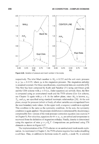
                            Figure 6.28. Variation of pressure and mach number in the nozzle.
                            respectively. The inlet Mach number is M in = 0.232 and the exit static pressure
                            is p / p 0 = 0.1135, where p 0 is the stagnation pressure. The stagnation enthalpy
                            is assumed constant. For these specifications, experimental data are available [45].
                            This flow has been computed by Karki and Patankar [31] using curvilinear grids
                            and the UDS scheme with µ = 0 (i.e., Euler equations are solved). Here, the flow
                            is computed using an unstructured mesh and the TVD scheme (Lin–Lin scheme,
                            see Chapter 3) again with µ = 0. At the inflow plane, since M in is known, u in ,
                            T in , and p in are specified using standard isentropic relationships [28]. At the exit
                            plane, except for pressure (which is fixed), all other variables are extrapolated from
                            the near-boundary node values. At the upper wall, a tangency condition is applied.
                            This condition is the same as the symmetry condition. At the axis, the symmetry
                            condition is again applied. The pressure distribution is determined by discretising a
                            compressible flow version of the total pressure-correction equation (see exercise 9
                            in Chapter 5). For velocities, equations for   = u 1 , u 2 are solved and temperature is
                            recovered from the definition of stagnation enthalpy. Finally, density is determined
                            using the equation of state p = ρ R g T . Computations are performed using 570
                            elements as shown in Figure 6.27.
                               The implementation of the TVD scheme on an unstructured mesh needs expla-
                            nation. As mentioned in Chapter 3, the TVD scheme requires four nodes straddling
                            a cell face. Thus, in addition to fictitious nodes P 2 and E 2 , a node W 2 is selected
   222   223   224   225   226   227   228   229   230   231   232