
Page 525 - Introduction to Information Optics
P. 525
510 9. Computing with Optics
a a a
2 "2 l "1 O "o
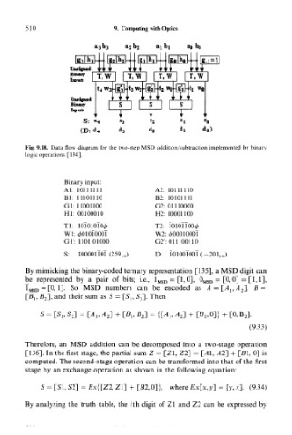
Fig. 9.18. Data flow diagram for the two-step MSD addition/subtraction implemented by binary
logic operations [134].
Binary input:
Al: 10111111 A2: 10111110
Bl: 11101110 B2: 10101111
Gl: 11001100 G2: 01110000
HI: 00100010 H2: 10001100
Tl: 10T01_Ol00 T2: TOIOTTOO^
Wl: 0010IOOOT W2: <£0001000l
Gl': 1101 01000 G2': 011100110
S: D: T0100TOOT(-201 10)
By mimicking the binary-coded ternary representation [135], a MSD digit can
be represented by a pair of bits; i.e., 1 MSD = [1,0], 0 MSD = [0,0] = [1,1],
I MSD=[0,1]. So MSD numbers can be encoded as A = [_A l,A 2], B =
[#!, J5 2], and their sum as S = [5 15 S 2]. Then
S = [Si,S 2] = LA,,A 2] + [B lf B 2 ] = {[A^AJ + [B l50]} + [0, B J.
(9.33)
Therefore, an MSD addition can be decomposed into a two-stage operation
[136]. In the first stage, the partial sum Z = [Zl, Z2] = [41, AT] + [Bl, 0] is
computed. The second-stage operation can be transformed into that of the first
stage by an exchange operation as shown in the following equation:
S = [SI, S2] = E.x{[Z2, Zl] + [B2,0]}, where £x[.x,y] = [y,x]. (9.34)
By analyzing the truth table, the /"th digit of Zl and Z2 can be expressed by