
Page 384 - Introduction to Marine Engineering
P. 384
354 Appendix
will be used to drive the rotating masses of the engine. The power
produced in the cylinder can be measured by. an engine indicator
mechanism as described in Chapter 2. This power is often referred to as
Indicated power'. The power output of the engine is known as 'shaft' or
'brake power'. On smaller engines it could be measured by applying a
type of brake to the shaft, hence the name.
Indicated power
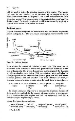
Typical indicator diagrams for a two-stroke and four-stroke engine are
shown in Figure A. 1. The area within the diagram represents the work
Firing
Firing
Compression
Atmospheric
tine Cylinder
volume
(a) Two stroke engine fb) Four stroke engine
Figure A.1 Indicator diagrams
done within the measured cylinder in one cycle. The area can be
measured by an instrument known as a 'planimeter* or by the use of the
mid-ordinate rule. The area is then divided by the length of the diagram
in order to obtain a mean height. This mean height, when multiplied by
the spring scale of the indicator mechanism, gives the indicated mean
effective pressure for the cylinder. The mean effective or 'average'
pressure can now be used to determine the work done in the cylinder.
Work done in = mean effective x area of piston X length of
1 cycle pressure (A) piston stroke
(Pm) (L)
To obtain a measure of power it is necessary to determine the rate of
doing work, i.e. multiply by the number of power strokes in one second.
For a four-stroke-cycle engine this will be rev/sec -r 2 and for a
two-stroke-cycle engine simply rev/sec.
power developed in one cylinder
_ mean effective area of length of piston no. of power
pressure (Pm) piston (A) stroke (L) strokes/sec (N)
= Pm L A N