
Page 385 - Introduction to Marine Engineering
P. 385
Appendix 355
For a multi-cylinder engine it would be necessary to multiply by the
number of cylinders.
Example
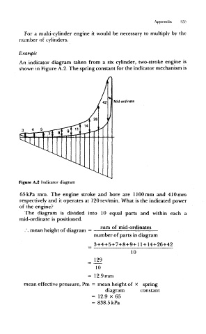
An indicator diagram taken from a six cylinder, two-stroke engine is
shown in Figure A.2. The spring constant for the indicator mechanism is
Mid ordinate
Figure A.2 Indicator diagram
65kPa mm. The engine stroke and bore are 1100mm and 410mm
respectively and it operates at 120rev/min. What is the indicated power
of the engine?
The diagram is divided into 10 equal parts and within each a
mid-ordinate is positioned.
, . , r . - sum of mid-ordinates
. . mean height of diagram = -
number of parts in diagram
= 3+4+5+7+8+9+ 11 + 144-264-42
10
10
= 12.9mm
mean effective pressure, Pm = mean height of x spring
diagram constant
= 12.9 x 65
= 838.5 kPa