
Page 390 - Introduction to Microcontrollers Architecture, Programming, and Interfacing of The Motorola 68HC12
P. 390
12.5 The 500 Series 367
12.5 The 500 Series
The 500 series of microcomputers are Reduced Instruction Set Computers (RISC) that
differs from Complex Instruction Set Computers (CISC) discussed heretofore. Its
registers are shown in Figure 12.11, and its instruction set is given in Table 12.7.
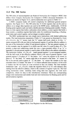
A RISC computer trades off control complexity for additional general purpose
registers. See Figure 12.11. The 500 series has 32 32-bit registers that can be used as
address or as integer data registers are used in the 68300 series. Additionally, 32 64-bit
floating-point registers each can hold a double-precision floating-point number. Finally,
there is a link register that holds a subroutine return address, a count register that holds a
loop counter, a condition register that holds codes for conditional branching, a floating-
point status and control register, and an integer exception register.
The RISC architecture has very simple move instructions with limited addressing
modes. The load instruction mnemonics (Table 12.7) are parsed as illustrated by lhau
r3,10 (r4 ): the "1" means load; the "h" means half-word, which is 16 bits; "u"
means unsigned (fill with zero bits) to load general register r3; and the effective address is
the sum of the instruction's offset 10 and general register 4. The last general register, r4
in this example, may be register 0, in which case the value 0 is used in place of it. This
permits a page-zero addressing mode but uses a sign-extended offset. If an "x" is
appended, a second general register is used in place of the offset in the address calculation.
The instruction lhaux r3, r4, r5 loads general register 3, as an unsigned number,
with the half-word, at the effective address which is the sum of general register 4 and
general register 5. In place of "1" the letters "st" cause the register to be stored, in
place of "h" the letter "b" causes eight bits to be moved or the letter "w" causes 16
bits to be moved; and in place of "u" the letter "a" causes the number to be sign
extended when it is loaded. The letter "r" in Ihbrx indicates byte reversal; a 16-bit word
is loaded, but the two bytes in it are reversed as they are loaded. The load multiple
instruction Imw r3,10 (r5 ) loads the registers from r3 to r31 with memory data
starting from the effective address, which is the contents of register 5 plus ten. The load
string instruction Iswx similarly loads string data into registers, but with more
complexity, which we skip in this introductory treatment. There are corresponding
integer store instructions and similar load and store instructions for floating-point and for
special-purpose registers.
Figure 12.11. User Registers for the 500 Series