
Page 392 - Introduction to Microcontrollers Architecture, Programming, and Interfacing of The Motorola 68HC12
P. 392
12.5 The 500 Series 369
appended, the overflow in the integer exception register is loaded with a two's-
complement overflow status bit; and if a period (.) is appended, the condition code
registers are updated for conditional branching. An appended letter "e" adds the previous
carry bit into the sum, in the manner of the ADC instruction, and another appended "m"
adds a minus 1 to it. An appended letter "i," as in addi r5, r6,7, indicates that the
sum put in r5 is source general register, r6 plus a 16-bit signed immediate operand, 7,
But if the source register is rO, the constant 0 is used instead of the contents of the source
register; this add immediate instruction is thus used to load immediate data into a general
register. Also, if a letter "s" is appended, as in addis, the immediate value can be added
to the high 16 bits of the destination general purpose register rather than the low-order 16
bits.
There are subtract instructions analogous to the add instructions. The letter "£" in
their mnemonics, as in subf r2 , r3, r4, just means subtract r3 "from" r4, putting
the result in r2. The multiply instruction can multiply a register's high word or low
word as signed or unsigned numbers, and a register's word value can be divided by
another register's word value as a signed or unsigned number. A register can be ANDed,
ORed, or exclusive-ORed with an immediate value (in the register's left 16 bits or right
16 bits) or another register, and source values can be complemented before being operated
on. The edit instructions include the logical shift left instruction slw, logical shift right
instruction srw, where the amount shifted is an immediate operand or the contents of
another general purpose register, and the sign extension instructions extsb and
extsh. The novel rlwinm edit instruction rotates the register contents left, and also
generates a mask that is ANDed with the result of stripping off some of the bits. It and
similar instructions can efficiently extract and insert bit fields in a struct.
The control instructions differ from the instruction sets discussed heretofore in the
way conditions are recorded and tested and the way a return address is saved and restored.
The conditional branches be, bca, bcl, and bcla test bits in the 32-bit condition
register. The branch address is a signed page-zero address (ba and bla) or a relative
address (b and bl). Four bits are typically used for each condition. Within each four-bit
set, the leftmost bit indicates less than; the next bit, greater than; the next bit, equal to;
and the last bit, indicating that the numbers are not able to be computed (an overflow
occurred) or compared (they are unordered). There are eight sets of these 4-bit conditions.
The leftmost set reflects integer arithmetic condition codes, modified by an arithmetic
instruction if a period is put at the end of the opcode mnemonic. A subsequent
conditional branch instruction reacts to the arithmetic instruction's result condition. The
second leftmost set reflects floating-point exceptions. The other six sets are updated by
compare instructions; some of its instruction bits designate which set in the condition
register is updated. In effect, the conditional branch instruction contains a bit number for
a bit in this condition register, and the branch takes place if the selected bit is true. There
are also similar unconditional branch instructions b, ba, bl, and bla.
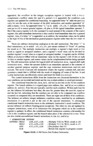
* SUBROUTINE DOTPRD
DOTPRD: MULU r26, r27, r28 ; Multiply V(0) by W(0), result in r26
MULU r3l,r29,r3Q ; Multiply V(l) by W(l), result in r31
ADD r31 f r31,r26 ; Dot product into r31
BLR ; Return link register to program counter
Figure 12.12. A 500 Series Dot Product Subroutine