
Page 103 - Introduction to Mineral Exploration
P. 103
86 C.J. MOON & M.K.G. WHATELEY
for drilling constructed so that the drill rigs can tainous areas. In areas without access prob-
be set on an almost horizontal surface. lems, typical drill hole patterns are square with
The pattern of drilling used is dependent a regular pattern or with rows of holes offset
on the assumed attitude and thickness of the from adjacent holes. The first hole normally
drilling target. This depends on the available aimed at the down dip projection of surface
information which may, of course, be inaccur- anomalies or the interpreted centre of subsur-
ate. Drilling often causes reconsideration of face geophysics. Most programs are planned
geological ideas and prejudices. Vertical bore- on the basis of a few test holes per target with a
holes are the easiest and cheapest to drill and review of results while drilling. The spacing
widely used for mineralisation with a shallow between holes will be based on anticipated
dip or for disseminated deposits. However, target size, previous company experience with
inclined holes are usually preferred for targets deposits of a similar type, and any information
with steep dips. The aim will be to cut the min- on previous competitor drilling in the district
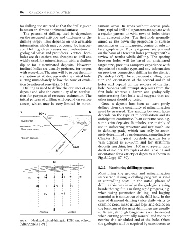
eralisation at 90 degrees with the initial hole, (Whateley 1992). The subsequent drilling loca-
cutting immediately below the zone of oxida- tion and orientation of the second and third
tion (weathered zone) (Fig. 5.11). holes will depend on the success of the first
Drilling is used to define the outlines of any hole. Success will prompt step outs from the
deposit and also the continuity of mineralisa- first hole whereas a barren and geologically
tion for purposes of resource estimation. The uninteresting first hole will suggest that an-
initial pattern of drilling will depend on surface other target should be tested.
access, which may be very limited in moun- Once a deposit has been at least partly
defined then the continuity of mineralisation
S N must be assessed. The spacing between holes
DDH 2
depends on the type of mineralisation and its
40° anticipated continuity. In an extreme case, e.g.
Overburden
Anomaly some vein deposits, boreholes are mainly of
use in indicating structure and not much use
Weathered zone 50° in defining grade, which can only be accur-
ately determined by underground sampling (see
“Fresh” Bedrock Chapter 10). Typical borehole spacing for a
Mineralisation EOH deposits anything from 100 m to several hun-
vein deposit is 25–50 m and for stratiform
dreds of meters. Examples of drill spacing and
orientation for a variety of deposits is shown in
Fig. 5.12 (pp. 87–89).
N
5.2.2 Monitoring drilling programs
Monitoring the geology and mineralisation
4 1 2 5 intersected during a drilling program is vital
in controlling costs. In the initial phases of
6 3 7 drilling this may involve the geologist staying
beside the rig if it is making rapid progress, e.g.
8 9 when using percussion drilling, and logging
material as it comes out of the drill hole. In the
case of diamond drilling twice daily visits to
examine core, make initial logs, and decide on
S the location of the next drill holes are usually
Anomaly Drill line sufficient, although longer visits will be needed
when cutting potentially mineralized zones or
FIG. 5.11 Idealized initial drill grid. EOH, end of hole. nearing the scheduled end of the hole. Often
(After Annels 1991.) the geologist will be required by contractors to