
Page 324 - System on Package_ Miniaturization of the Entire System
P. 324
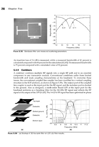
298    Cha pte r  F i v e


                                                          0
                                                          –5
                                                         –10
                                                       Magnitude (dB)  –20  S 21  S 11
                                                         –15


                                                         –25
                                                         –30
                                                         –35
                                                         –40
                                                           12        13       14        15        16        17        18
                                                                      Frequency (GHz)
                    FIGURE 5.35  Bandpass fi lter and measured scattering parameters.


                    An insertion loss of 3.4 dB is measured, while a measured bandwidth of 41 percent is
                    calculated compared with 69 percent for the simulation [62,65]. The measured bandwidth
                    is 75 percent compared with a simulated value of 92 percent.

                    5.4.9 Combiners
                    A combiner combines multiple RF signals into a single RF path and is an essential
                    component in any transceiver module. Conventional combiners suffer from limited
                    bandwidth and weak coupling characteristics at the baseband. To overcome these
                    issues, the conventional coupled line coupler has been modified to a vertical coupling
                    structure in the SOP platform, as shown in Figure 5.39a. The output port of the coupled
                    line coupler is used as the input port for the RF signal, and the isolation port is shorted
                    to the ground. Also as designed, a ninth-order Bessel LPF at the input port for the
                    baseband performs as a bandstop filter for the 14-GHz RF signal and reflects the RF
                    signal at the output of the LPF [61,65]. The 14-GHz RF signal has been optimized in-phase


                                                       0
                                      Top layer
                                                     −10
                                                    S 11  and S 21  [dB]
                                      Dielectric
                                      Slotted ground  −20

                                      Dielectric     −30
                                                     −40    S 11  (Measured)
                                                            S 11  (Simulated)
                                      Bottom layer          S 21  (Measured)
                                                            S 21  (Simulated)
                                                     −50
                                                          8.5   9   9.5  10  10.5  11  11.5
                                                                    Frequency [GHz]
                           (a)                                           (b)
               FIGURE 5.36  (a) Stackup of 3D four-pole fi lter on LCP. (b) Filter results.