
Page 366 - System on Package_ Miniaturization of the Entire System
P. 366
338 Cha pte r S i x
compatibility with an ISA bus or a Micro Channel bus. Ordinary PC add-in cards can be
placed several meters from a PC, to which they are connected via the optical link [44].
The link converts the parallel signals on the PC’s I/O bus into serial format, preserving
the coherency of the bus protocol, and then transmits them via an optical fiber. Since the
optical communication link is perfectly transparent to add-in cards and software,
programs can directly access add-in cards placed at a distance from the PC as if they
were installed in the PC box. The maximum distance is 100 m for the ISA bus and 10 m
for the Micro Channel bus.
Unfortunately the work on card-to-card optical links for enhancing network
connectivity and performance stopped at this point. A few years later both NTT and NEC
published results of their development work on optically linking printed circuit boards in
their mainframes. In this case, either optical fiber arrays or arrays of polymer waveguides
are used in conjunction with miniaturized optical transceivers containing arrays of lasers,
photodetectors, and associated amplifiers and laser drivers. The transceivers used for
card-to-card optical communication are miniaturized versions of bulkier optical
transceivers used in the optical communication industry. The substantial decrease in form
factor is made possible by running the lasers uncooled. The work from NEC [26,42–43],
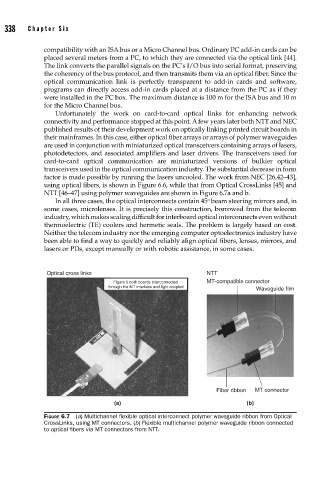
using optical fibers, is shown in Figure 6.6, while that from Optical CrossLinks [45] and
NTT [46–47] using polymer waveguides are shown in Figure 6.7a and b.
o
In all three cases, the optical interconnects contain 45 beam steering mirrors and, in
some cases, microlenses. It is precisely this construction, borrowed from the telecom
industry, which makes scaling difficult for interboard optical interconnects even without
thermoelectric (TE) coolers and hermetic seals. The problem is largely based on cost.
Neither the telecom industry nor the emerging computer optoelectronics industry have
been able to find a way to quickly and reliably align optical fibers, lenses, mirrors, and
lasers or PDs, except manually or with robotic assistance, in some cases.
Optical cross links NTT
Figure 5 both boards interconnected MT-compatible connector
through the MT interface and light coupled
Waveguide film
Fiber ribbon MT connector
(a) (b)
FIGURE 6.7 (a) Multichannel fl exible optical interconnect polymer waveguide ribbon from Optical
CrossLinks, using MT connectors. (b) Flexible multichannel polymer waveguide ribbon connected
to optical fi bers via MT connectors from NTT.