
Page 142 - Sami Franssila Introduction to Microfabrication
P. 142
Etching 121
may not tolerate higher temperatures, or the etch may cannot be used to make fine features (Figure 11.2).
evaporate. Changing concentration can either increase Undercutting is similar to vertical etched depth. For
or decrease etch rate: silicon etch rate increases from a thin-film thickness of 500 nm, undercutting is also
0 to 20% KOH concentration, and decreases for 500 nm, and etch bias, that is, the difference in etched
higher concentrations. feature size to mask size, is 1000 nm.
The oxide etch rate goes down linearly with decreas- The isotropic profile is the most commonly encoun-
ing HF concentration. However, the aluminium etch rate tered etch profile. Most wet etchants result in an
goes up when HF concentration decreases: 49% HF isotropic profile, and it is also encountered in plasma
etches aluminium 38 nm/min, but HF:H 2 O (1:10) results and dry etching. Dry etching of silicon with XeF 2 gas,
in 320 nm/min rate. This is because water has an active without plasma, results in isotropic profiles. Similarly,
role in aluminium surface oxidation. Buffering agents
HF-vapour etching of oxide is isotropic dry etching. In
and other additives can dramatically change etch rates,
plasma etching, the degree of isotropy can be controlled
as shown in Table 11.3.
by the etching parameters, from fully isotropic to fully
Wet etching is an indispensable tool in defect anisotropic (which may not be easy).
analysis: microstructural defects like stacking faults Undercutting can be compensated by making the
and pinholes can be made visible by wet etching. initial mask feature larger than the desired width, for
Sirtl, Secco, Wright, Dash and Sailor are etchants for light field structures and vice versa for dark field
delineating defects.
structures. This approach works quite well for isolated
structures, but in dense arrays its utility is compromised.
Wet etching profiles are seldom perfectly isotropic,
11.1.2 Etching profiles
and both deep slopes and gently sloping sidewall profiles
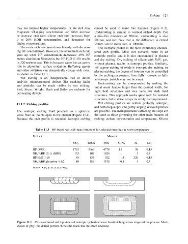
The isotropic etching front proceeds as a spherical are possible. The main parameters affecting the slope are
wave from all points open to the etchant (Figure 11.1). the same as those governing the other main features of
Because the etch profile is rounded, isotropic etching etching: etchant concentration and temperature. Silicon
Table 11.3 HF-based wet etch rates (nm/min) for selected materials at room temperature
Etchant Material
SiO 2 TEOS PSG Si 3 N 4 Al Mo
HF (49%) 1763 3969 4778 15 38 0.15
NH 4 F:HF (7:1) (BHF) 133 107 1024 1 3 0.5
HF:H 2 O 1:10 48 157 922 1.5 320 0.15
NH 4 F:HF:glycerine 4:1:2 89 186 1375 0.8 1 0.3
Source: Kim, B.-H. et al. (1999).
Figure 11.1 Cross-sectional and top views of isotropic (spherical wave front) etching at two stages of the process. Mask
shown in gray; the dotted portion shows the mask that has been undercut