
Page 220 - Materials Chemistry, Second Edition
P. 220
206 LIFE CYCLE ASSESSMENT HANDBOOK
Nuclear Based Hydrogen Production
GaBi 4 process plan:Reference quantities
Construction of Nuclear ISl Consruction of Hydrogen ISl
Plant Plant
Fuel Process E| Utilization of Nuclear Plant Ε3Γ " * Utilization of Hydrogen XES)
•4 L Plant
Heavy Water ProductiorXEl
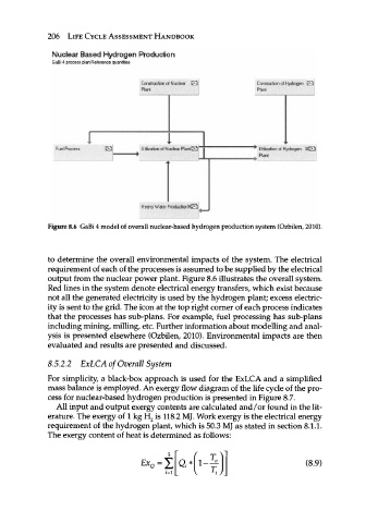
Figure 8.6 GaBi 4 model of overall nuclear-based hydrogen production system (Ozbilen, 2010).
to determine the overall environmental impacts of the system. The electrical
requirement of each of the processes is assumed to be supplied by the electrical
output from the nuclear power plant. Figure 8.6 illustrates the overall system.
Red lines in the system denote electrical energy transfers, which exist because
not all the generated electricity is used by the hydrogen plant; excess electric-
ity is sent to the grid. The icon at the top right corner of each process indicates
that the processes has sub-plans. For example, fuel processing has sub-plans
including mining, milling, etc. Further information about modelling and anal-
ysis is presented elsewhere (Ozbilen, 2010). Environmental impacts are then
evaluated and results are presented and discussed.
8.5.2.2 ExLCA of Overall System
For simplicity, a black-box approach is used for the ExLCA and a simplified
mass balance is employed. An exergy flow diagram of the life cycle of the pro-
cess for nuclear-based hydrogen production is presented in Figure 8.7.
All input and output exergy contents are calculated and/or found in the lit-
erature. The exergy of 1 kg H 2 is 118.2 MJ. Work exergy is the electrical energy
requirement of the hydrogen plant, which is 50.3 MJ as stated in section 8.1.1.
The exergy content of heat is determined as follows:
T
ΕΧ (8.9)
Ω=Σ Qi*
2=1 l < /