
Page 233 - Lindens Handbook of Batteries
P. 233
ZINC-CARBON BATTERIES—LECLANCHÉ AND ZINC CHLORIDE CELL SYSTEMS 9.27
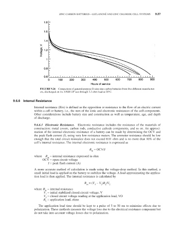
FIGURE 9.26 Comparison of general-purpose D-size zinc-carbon batteries from five different manufactur-
ers, discharged on the ANSI LIF test through 2.2 ohm load at 20°C.
9.6.6 Internal Resistance
Internal resistance (Rin) is defined as the opposition or resistance to the flow of an electric current
within a cell or battery, i.e., the sum of the ionic and electronic resistances of the cell components.
Other considerations include battery size and construction as well as temperature, age, and depth
of discharge.
9.6.6.1 Electronic Resistance. Electronic resistance includes the resistance of the materials of
construction: metal covers, carbon rods, conductive cathode components, and so on. An approxi-
mation of the internal electronic resistance of a battery can be made by determining the OCV and
the peak flash current (I), using very low resistance meters. The ammeter resistance should be low
enough that the total circuit resistance does not exceed 0.01 ohm and is no more than 10% of the
cell’s internal resistance. The internal electronic resistance is expressed as
R = OCV/I
in
where R = internal resistance expressed in ohm
in
OCV = open circuit voltage
I = peak flash current (A)
A more accurate method of calculation is made using the voltage-drop method. In this method, a
small initial load is applied on the battery to stabilize the voltage. A load approximating the applica-
tion load is then applied. The internal resistance is calculated by
R = (V - V )R /V 2
in
2
L
1
where R = internal resistance
in
V = initial stabilized closed-circuit voltage, V
1
V = closed circuit voltage reading at the application load, VO
2
R = application load, ohms
L
The application load time should be kept to a pulse of 5 to 50 ms to minimize effects due to
polarization. These methods measure the voltage loss due to the electrical resistance component but
do not take into account voltage losses due to polarization.