
Page 234 - Lindens Handbook of Batteries
P. 234
9.28 PRIMARY BATTERIES
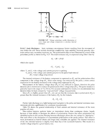
FIGURE 9.27 Voltage pulse/time profile illustration of
curve shape and voltage components to calculate internal
resistance.
9.6.6.2 Ionic Resistance. Ionic resistance encompasses factors resulting from the movement of
ions within the cell. These include electrolyte conductivity, ionic mobility, electrode porosity, elec-
trode surface area, secondary reactions, etc. The polarization effect is best illustrated by a trace of the
pulse/time profile as shown in Fig. 9.27. The total resistance (R ) is expressed using Ohm’s law by
T
R = dR = dV/dI
T
which also equals
(V - V )/(I - I )
2
1
2
1
where V and I = the voltage and current just prior to pulsing
1
1
V and I = the voltage and current just prior to the pulse load removal
2
2
dV = total voltage drop shown
3
The internal resistance of the battery component is expressed as dV and the polarization effect
1
component is the voltage drop dV . Since some energy was removed by the pulse, a more correct
2
expression for the battery resistance is the voltage drop expressed by dV .
4
Measurement of the battery voltage drop (dV ) is very difficult to capture, therefore the pulse
4
duration (dt) is minimized to reduce the polarization effect voltage drop (dV ). The pulse duration is
2
generally kept in the range of 5 to 50 ms. For accurate and repetitive results, it is recommended that
duration times be kept constant by “read and hold” voltage measurements.
Since dV is slightly greater than dV , one can see that the resistance due to polarization (R ) is
1
p
2
greater than the internal resistance of the battery (R ) by the formula
ir
R = R + R
T ir p
Partial, light discharge or a light background load prior to the pulse and internal resistance mea-
surements provides equilibration for consistent measurements.
Table 9.6 shows the general relationship of flash current and internal resistance of the more
popular cell sizes.
Zinc-carbon batteries perform better on intermittent drains than continuous drains, largely
because of their ability to dissipate the effects of polarization. Factors that affect polarization are
identified earlier in this section. Resting between discharges allows the zinc surface to “depolarize.”
One such effect is the dissipation of concentration polarization at the anode surface. This effect is
more pronounced as heavier drains and longer duty schedules are applied. The internal resistance
of the zinc chloride batteries is slightly lower than that of the Leclanché batteries. This results in a
smaller voltage drop for a given battery size.