
Page 274 - Lindens Handbook of Batteries
P. 274
11.12 pRIMARy BATTERIES
the cathode. The cathode mix can be added to the can in two ways, depending on the battery manu-
facturer’s equipment setup. In one process, a prescribed amount of compacted mixture of manganese
dioxide, carbon, and other additives are added to the can. The cathode is then directly molded into
the can by inserting a ram down the center of the mix. This compacts the cathode mix to the required
solids packing and provides a good can-to-cathode contact. The second method, and currently the
most common one, is that the cathode mix is first formed into cylindrical rings outside of the cell,
then three or four such rings are inserted into the can. Next, separator strips are inserted into the
hollow cavity of the rings using either the two-strip method or a convolute separator. Once the sepa-
rator is in place, the required amount of anode gel is added based on precise calculations, whereas
the input capacity of the anode is close to or slightly greater than that of the cathodes. This required
ratio is to prevent excessive gassing if and when the cell is deeply discharged. Next, the collector
assembly is added and the can crimped over it to provide a leakproof seal. The brass collector pin
now provides the external contact for the negative electrode. The cell now has top and bottom cov-
ers added to it and then the plastic label is applied. The covers serve a twofold purpose. In addition
to providing a label with the manufacturer’s distinctive artwork, it also indicates the polarity of the
cell. This ensures that the customer will properly position the battery in a device for proper opera-
tion. This becomes increasingly important for a device that takes multiple batteries as one inserted
backwards could be charged by the others, causing the cell to prematurely leak. In order to prevent
this, some manufacturers have also added a reversal protection, which consists of an insulating ring
on the positive end of the cell.
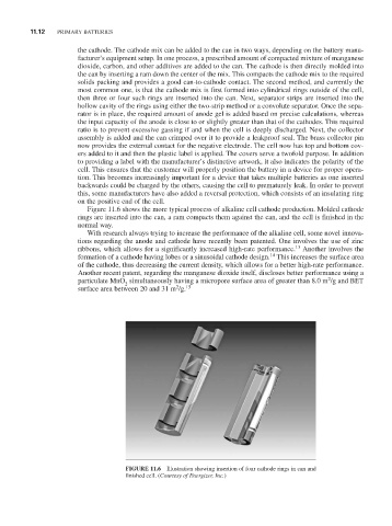
Figure 11.6 shows the more typical process of alkaline cell cathode production. Molded cathode
rings are inserted into the can, a ram compacts them against the can, and the cell is finished in the
normal way.
With research always trying to increase the performance of the alkaline cell, some novel innova-
tions regarding the anode and cathode have recently been patented. One involves the use of zinc
13
ribbons, which allows for a significantly increased high-rate performance. Another involves the
14
formation of a cathode having lobes or a sinusoidal cathode design. This increases the surface area
of the cathode, thus decreasing the current density, which allows for a better high-rate performance.
Another recent patent, regarding the manganese dioxide itself, discloses better performance using a
2
particulate MnO simultaneously having a micropore surface area of greater than 8.0 m /g and BET
2
2
surface area between 20 and 31 m /g. 15
FiguRE 11.6 Illustration showing insertion of four cathode rings in can and
finished cell. (Courtesy of Energizer, Inc.)