
Page 227 - MEMS Mechanical Sensors
P. 227
216 Flow Sensors
means that the fluid layers mix. The streamlines are curled [Figure 9.3(b)]. The reader
is referred to the book by Koch et al. [4] for the theory of microfluidic flow. General
information on fluid mechanics can be found in [33, 34]. It also should be noted that
there are two essentially different flow profiles of laminar flow within channels. The
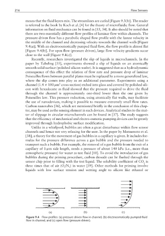
pressure-driven flow has a parabolic shaped flow profile with the fastest velocity in
the middle of the channel and decreasing velocity towards the channel walls [Figure
9.4(a)]. With an electroosmotically pumped fluid flow, the flow profile is almost flat
[Figure 9.4(b)]. For open flow (pressure driven), large flow velocity gradients occur
close to the wall [Figure 9.4(c)].
Recently, researchers investigated the slip of liquids in microchannels. In the
paper by Tabeling [35], experiments showed a slip of liquids on an atomically
smooth solid surface (polished silicon wafer). It is suggested that as a hydrodynamic
consequence of this effect the relation of flow rate and pressure drop of laminar
Poiseuilles flows between parallel plates must be replaced by a more generalized law,
where the slip comes into play as an additional parameter. Experiments using a
2
channel (1.4 × 100 µm cross-section) etched into glass and covered by polished sili-
con with hexadecane as fluid showed that the pressure required to drive the fluid
through the channel is approximately one-third lower than the one given by
Poiseuilles law. This pressure reduction, using atomically flat walls, may facilitate
the use of nanodevices, making it possible to measure extremely small flow rates.
Carbon nanotubes [36], which are mentioned briefly in the conclusion of this chap-
ter, may be used as the sensing element in such devices. Analytical studies to the mat-
ter of slippage in circular microchannels can be found in [37]. The study suggests
that the efficiency of mechanical and electro-osmotic pumping devices can be greatly
improved through hydrophobic surface modification.
Unlike in a whirlpool, bubbles are often a great disturbance within flow sensor
channels and hence not very relaxing for the user. In the paper by Matsumoto et al.
[38], a theory for the movement of gas bubbles in a capillary is given. It includes for-
mulas for the pressure difference across a gas bubble and the pressure needed to
transport such a bubble. For example, the removal of a gas bubble from the exit of a
capillary of 1-µm side length, needs a pressure of about 140 kPa (i.e., more than
atmospheric pressure) for water as test fluid [10]. To avoid the introduction of gas
bubbles during the priming procedure, carbon dioxide can be flushed through the
sensor chip prior to filling with the test liquid. The solubility coefficient of CO is
2
three times that of air (O /N ) in water [39]. Other methods for priming involve
2 2
liquids with low surface tension and wetting angle to silicon like ethanol or
(a) (b) (c)
Figure 9.4 Flow profiles: (a) pressure driven flow in channel; (b) electroosmotically pumped fluid
flow in channel; and (c) open flow (pressure driven).