
Page 231 - MEMS Mechanical Sensors
P. 231
220 Flow Sensors
suspended sensor setup has a far better sensitivity. This sensor chip has a very high
pressure drop due to the small channel size. A three-dimensional anemometer was
presented by Ebefors et al. [64] and is described later within the turbulent flow
measurement section. Using the same fabrication technology as for the drag force
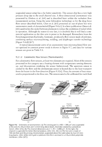
flow sensor described below, Chen et al. [65] presented an out-of-plane hot wire
anemometer made of chrome/nickel [Figure 9.6(c)]. In a later publication Chen et al.
[66] sandwiches the nickel between platinum to reduce the oxidation of nickel while
in operation. Although the sensor is very fast, it is doubtful that it will find a com-
mercial application as the thin wire is prone to be damaged. Researchers from the
Forschungszentrum Karlsruhe, Germany, produced a flow sensor made of polymer,
combining surface micromachining, molding, and diaphragm transfer technology
[Figure 9.6(d)] [67].
A typical measurement curve of an anemometer type micromachined flow sen-
sor operated in constant power mode is shown in Figure 9.7, and data for various
sensors are given in Table 9.1.
9.2.1.2 Calorimetric Flow Sensors (Thermotransfer)
For calorimetric flow sensors, at least two elements are required. Most of the sensors
presented in this category use a heating element with temperature sensing elements
up- and downstream rendering the sensor bidirectional. The upstream sensor is
cooled by the flow and the downstream sensor is heated due to the heat transport
from the heater in the flow direction [Figure 9.5(b)]. Thus, the amount of heat meas-
ured is proportional to the flow rate. The sensors need to be calibrated for each fluid
Inlet
Flow Channel Inlet Nitride
Temperature
Heating sensitive diodes Silicon Heater Heater
resistor base
Nitride
Polyimide Cantilever Suspended
insulator
Outlet channel
Outlet
(a) Silicon Silicon
(b)
Hot wire
Flow Polymer
Inlet housing Outlet
Support beam/ Hot wire
electrical lead
Flow
Bond
pad Bending Polyimide Fluid
joint membrane channel
(c) (d)
2
Figure 9.6 Schematics of anemometers: (a) The sensing part is a 400 × 300-µm area suspended
at the end of a 30-µm-thick and 1.6-mm-long silicon beam, thermally isolated by a polysilicon
3
trench. (After: [55].) (b) The channel dimensions are 2 × 20 × 2,000 µm . At the right, the
channel is suspended for better thermal isolation. (After: [44, 45].) (c) The hot wire is made of
100-nm-thick and 50-µm-long chrome/nickel, suspended above the wafer plane by two 0.4-mm-
long beams. (After: [65].) (d) A gold or platinum thin-film is enclosed in a 2.4-µm-thick polyimide
membrane. (After: [67].)