
Page 232 - MEMS Mechanical Sensors
P. 232
9.2 Thermal Flow Sensors 221
Table 9.1 Data for Anemometer Type Flow Sensors
Author; Year Flow Range Sensitivity Response Time Fluid Chip Size
Stemme et al. 0.8–30 m/s 0.01–0.5 50 ms Air —
[55]; 1986 (mW/m/s)/(mW)
Ebefors et al. 0–60 l/min — 120–330 µs Air 3.5 × 3 × 0.5
[64]; 1998 mm 3
Wu et al. [44, <20 nl/min; 8, 40, and 180 — Water —
45]; 2000, 2001 resolution: 0.4 ppm/(nl/min)
nl/min
Chen et al. [65]; — — 50 µs — —
2002
1
Dittmann et al. 0.1–500 sccm ; — — Nitrogen 5.5 × 4.5 × 1.2
[67]; 2001 1 µl/min to 2.5 Water mm 3
ml/min
1 sccm = 1 ml/min
1
as the transported heat is connected to the fluid parameter (e.g., the specific heat or
the thermal conductivity). For various flow measurement ranges, the distance
between the sensors can be adjusted symmetrically up- and downstream of the
heater. The output signal is the difference in temperature between the up- and
downstream sensors. The prominent measurement circuit is the Wheatstone bridge.
Calorimetric flow sensors are able to operate at very low flow rates. A few examples
of calorimetric flow sensors are presented below. Table 9.2 gives the reader an idea
about the measured flow ranges, sensitivities, and sensor dimensions.
The sensor by Glaninger et al. [50] has thin-film germanium thermistors used as
heater and temperature sensors. The flow sensor chip from Oda et al. [53] is com-
posed of one heater and four thermopiles, consisting of 9 or 23 thermocouples each,
and has a dynamic range of 1:1000 for air flow measurements. A sensor fabricated
only by CMOS compatible technology was presented by Häberli et al. [54]. Lyons
et al. [49] use silicon-carbide heater and sensing elements due to the excellent
mechanical stability (better than silicon by a factor of 2 to 4) and thermal stability
(melting point of silicon-carbide is 2,800°C). The devices are able to sustain harsh
environmental and operating conditions. Porous silicon, as thermal isolation, was
used by Kaltsas et al. [52]. The very small sensor chip has a polysilicon heater and
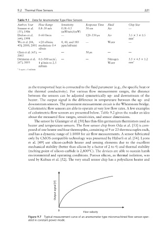
[V]
signal
Output
0
Flow velocity
Figure 9.7 Typical measurement curve of an anemometer type micromachined flow sensor oper-
ated in constant power mode.