
Page 234 - MEMS Mechanical Sensors
P. 234
9.2 Thermal Flow Sensors 223
Thermopile
Heater
Sensor
Electronics
Heater
Flow Flow
(a) (b)
Figure 9.8 (a, b) Schematics of velocity and direction-sensitive flow sensors. (a) (After: [28]); and
(b) (After: [29]).
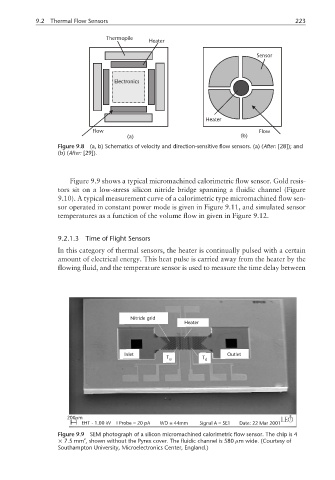
Figure 9.9 shows a typical micromachined calorimetric flow sensor. Gold resis-
tors sit on a low-stress silicon nitride bridge spanning a fluidic channel (Figure
9.10). A typical measurement curve of a calorimetric type micromachined flow sen-
sor operated in constant power mode is given in Figure 9.11, and simulated sensor
temperatures as a function of the volume flow in given in Figure 9.12.
9.2.1.3 Time of Flight Sensors
In this category of thermal sensors, the heater is continually pulsed with a certain
amount of electrical energy. This heat pulse is carried away from the heater by the
flowing fluid, and the temperature sensor is used to measure the time delay between
Nitride grid
Heater
Inlet Outlet
T u T d
µ
200 m
EHT - 1.00 kV I Probe = 20 pA WD = 44mm SignalA=SE1 Date: 22 Mar 2001
Figure 9.9 SEM photograph of a silicon micromachined calorimetric flow sensor. The chip is 4
2
× 7.5 mm , shown without the Pyrex cover. The fluidic channel is 580 µm wide. (Courtesy of
Southampton University, Microelectronics Center, England.)