
Page 235 - MEMS Mechanical Sensors
P. 235
224 Flow Sensors
Metal
resistor
Nitride
grid
10 m EHT = 1.00 kV I Probe = 10 pA WD=20mm SignalA=SE1 Date: 22 Mar 2001
µ
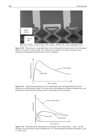
Figure 9.10 The picture is a magnified view of the nitride grid with gold resistors from the figure
above. The nitride is 160 nm thick. The resistor lines are about 5 µm wide. (Courtesy of the
University Southampton Microelectronics Center, England.)
difference Cooling part
Temperature Linear part
0 Flow velocity
Figure 9.11 Typical measurement curve of a calorimetric type micromachined flow sensor
operated in constant power mode. The curve shows the temperature difference between up- and
downstream sensor elements. Measurements can be taken at the linear part.
Heater temperature
Temperature
T d
Linear part
∆T Cooling part
T u
0 Flow velocity
Figure 9.12 Simulated sensor temperatures as function of the volume flow. T and T are the
u d
upstream and downstream sensor temperatures. ∆T is the temperature difference between T and
u
T .(After: [43].)
d