
Page 236 - MEMS Mechanical Sensors
P. 236
9.2 Thermal Flow Sensors 225
heat source and heat detection [Figure 9.5(c)]. The time of flight mode is the least
sensitive to changes in ambient temperature as the time of arrival of the heat pulse
maxima are measured. A minimum of two wires is needed. A third wire renders the
sensor bidirectional. The time of flight mode works best in a regime of large flow
velocities. In this case, the shape of the heat pulse is not seriously deformed by diffu-
sion, which leads to sharp signals [12]. The measurement range can be set by the dis-
tance between the heat source and the heat detection. For lower flow rates, the
distance needs to be short, and for large flow rates the distance should be large.
However, the fluid flow will broaden the signal and if the detector is too far away
from the source, the signal pulse is broadened so much that a peak cannot be
distinguished.
This category of thermal flow sensors has not been used as often as anemome-
ters or calorimeters. A silicon micromachined time of flight flow sensor in combina-
tion with an anemometer was presented by Ashauer et al. [41] and was described
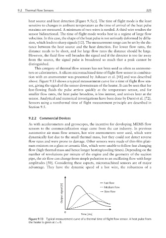
above. Figure 9.13 shows a typical measurement curve for a time of flight flow sen-
sor, giving the signal of the sensor downstream of the heater. It can be seen that for
fast-flowing fluids the pulse arrives quickly at the temperature sensor, and for
smaller flow rates, the heat pulse broadens, is less intense, and arrives later at the
sensor. Analytical and numerical investigations have been done by Durst et al. [72].
Sensors using a nonthermal time of flight measurement principle are described in
Section 9.5.
9.2.2 Commercial Devices
As with accelerometers and gyroscopes, the incentive for developing MEMS flow
sensors to the commercialization stage came from the car industry. In previous
automotive air mass flow sensors, hot wire anemometers were used, which were
dynamically fast due to the small thermal mass, but they could not detect reverse
flow rates and were prone to damage. Other sensors were made of thin-film plati-
num resistors on a glass or ceramic film, which were unable to follow fast changing
flow (high thermal mass and hence longer heating/cooling times). Depending on the
number of revolutions per minute of the engine and the geometry of the suction
pipe, the air flow can change from simple pulsation to an oscillating flow with large
amplitudes [50]. Considering these aspects, micromachined sensors are of major
advantage. They have the dynamic speed of a hot wire, the robustness of a
Fast flow
[V] Medium flow
signal Slow flow
Output
0
Time [ms]
Figure 9.13 Typical measurement curve of a thermal time of flight flow sensor. A heat pulse from
the heater is given at t =0.