
Page 233 - MEMS Mechanical Sensors
P. 233
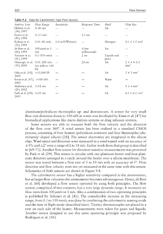
222                                                                    Flow Sensors

          Table 9.2  Data for Calorimetric Type Flow Sensors
          Author; Year  Flow Range  Sensitivity    Response Time  Fluid       Chip Size
          Häberli et al.  0–40 m/s  —              —              Air         —
          [54]; 1997
          Lyons et al.  0–3.5 m/s  —               2.5 ms         —           —
          [49]; 1998
          Kaltsas et al.  0.41–40 cm/s  6.0 (mV/W)/(m/s)  —       Nitrogen    1.1 × 1.5 mm 2
          [52]; 1999
          de Bree et al.  100 µm/s to 1  —         A few          Air         —
          [68]; 1999   m/s                         milliseconds
          Ashauer et al.  0.1–150 mm/s  —          2 ms           Liquids and  —
          [41]; 1999                                              gases
          Glaninger et al. 0.01–200 m/s;  —        20 ms          Air         2 × 4 × 0.3
          [50]; 2000   0.6 ml/h to 150                                        mm 3
                       l/h
          Oda et al. [53]; <12,000 l/h  —          —              Air         2 × 2mm 2
          2002
          Ernst et al. [47]; >100 nl/h  —          —              Water       —
          2002
          Makinwa et al. 2–18 m/s  —               —              Air         4 × 4mm 2
          [28]; 2002
          Park et al. [29]; 5–10 m/s  —            —              Air         6.2 × 6.2 mm 2
          2003


                 aluminum/polysilicon thermopiles up- and downstream. A sensor for very small
                 flow rate detection down to 100 nl/h in water was developed by Ernst et al. [47] for
                 biomedical applications like micro dialysis systems or drug infusion systems.
                    Some sensors are able to measure both the flow velocity and the direction
                 of the flow over 360°. A wind sensor has been realized in a standard CMOS
                 process, consisting of four heaters (polysilicon resistors) and four thermopiles (alu-
                         +
                 minum/p -doped silicon) [28]. The sensor electronics are integrated in the silicon
                 chip. Wind speed and direction were measured in a wind tunnel with an accuracy of
                 ±4% and ±2° over a range of 2 to 18 m/s. Earlier work from that group is described
                 in [69–71]. Another flow sensor for direction-sensitive measurements was presented
                 by Park et al. [29]. This sensor is circular with one platinum heater and four plati-
                 num detectors arranged in a circle around the heater over a silicon membrane. The
                 sensor was tested between a flow rate of 5 to 10 m/s with an accuracy of 5°. Flow
                 direction and flow velocity were not yet measured at the same time with this sensor.
                 Schematics of both sensors are shown in Figure 9.8.
                    The calorimetric sensor has a higher sensitivity compared to the anemometer,
                 but at larger flow velocities the anemometer becomes advantageous. Hence, de Bree
                 et al. [68] developed a flow sensor operated by using both principles. The flow
                 sensor, comprised of two resistors, has a very large dynamic range. It measures air
                 flow rates from 100 µm/s to 1 m/s. Also a combination of two operating principles
                 is published by Ashauer et al. [41]. The considerable increase in the measuring
                 range, from 0.1 to 150 mm/s, was done by combining the calorimetric sensing mode
                 and the time of flight mode (described later). Twenty thermocouples are placed in a
                 row on each side of the heater. Measurements were taken for gases and liquids.
                 Another sensor designed to use this same operating principle was proposed by
                 Rodrigues et al. [56].