
Page 228 - MEMS Mechanical Sensors
P. 228
9.2 Thermal Flow Sensors 217
isopropanol [39]. After priming, the system has to be flushed for a long time with
the working liquid in order to remove the alcohol completely. Prior degassing of the
liquids [39] or the use of high pressure for a short time to wash out the bubbles [4]
may be successful.
As one can see, flow sensing is very complex. Fluid flow is already a science by
itself, and furthermore, various principles can be used for flow sensing.
9.2 Thermal Flow Sensors
The overwhelming majority of micro flow sensors described so far work in the ther-
mal domain. It is also thermal flow sensors that are produced commercially million
fold. They are placed in car air intake systems used for motor efficiency control and
in air conditioning systems. The commercial production of flow sensors began only
about 8 years ago with the replacement of conventional flow sensors in cars [40]. In
this section, mostly recent publications have been cited, but there are numer-
ous other publications from the last 20 years that deal with thermal flow sen-
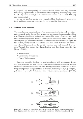
sors. Thermal flow sensors have been classified into three basic categories (see
Figure 9.5 [41]):
• Anemometers;
• Calorimetric flow sensors;
• Time of flight sensors.
For most materials, the electrical resistivity changes with temperature. There-
fore, this parameter has been chosen for the thermal flow measurements. Various
materials have been used to form resistors. The higher the TCR, the better the sensi-
tivity to temperature changes and thus to flow rate. Platinum [17, 29, 42], gold [43],
polysilicon [44, 45], Ni-ZrO cermet films [46], amorphous germanium [47, 48],
2
P el T
Flow
(a) Q
Heater = T sens
∆T
P el
Flow Q
(b)
T sens1 Heater T sens2
∆T
P el
Flow
(c) Q
Heater T sens
Figure 9.5 Schematic of the working principles of thermal flow sensors: (a) anemometer (heat
loss), (b) calorimetric flow sensors (thermotransfer), and (c) time of flight sensors. (After: [41].)