
Page 242 - MEMS Mechanical Sensors
P. 242
9.3 Pressure Difference Flow Sensors 231
Capacitive
Flow restriction pressure sensors
++
p -silicon
p 1
Pyrex
Silicon
p 2 p 2
p 1
Glass Pyrex
p 1 p 2 Input Flow Output
Inlet Capacitor flow channel
Outlet flow
(a) (b)
Flow restriction
Sensor
diaphragm
Flow
Piezoresistor ZnO thin film ring
Polyimide
p 2
membrane Sensor A Sensor B
p 1
Silicon
Orifice Silicon
Inlet Outlet
Flow restriction
(c) (d)
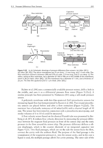
Figure 9.22 (a, b) Schematic drawings of pressure difference flow sensors: (a) (After: [81].)
(b) (After: [82, 83].) The silicon membranes are 25 µm thick, 1.5 mm long, and 1.5 mm wide. The
flow restriction channel is between 200 and 570 µm wide, 2.9 mm long, and 21 µm deep. (c) The
orifice, acting as flow restriction, has a diameter of 100 to 400 µm in the middle of the membrane,
which is 20 µm thick. (After: [84].) (d) The membrane has a diameter of 1 mm, and a thickness of
25 µm. The thin-film sputtered ZnO is 1 µm thick. (After: [85].)
Richter et al. [84] uses a commercially available pressure sensor, drills a hole in
the middle, and uses it as a differential pressure flow meter [Figure 9.22(c)]. A
similar principle has been presented by Nishimoto [85] using a self-made pressure
sensor.
A polyimide membrane with thin-film sputtered ZnO piezoelectric sensors for
measuring liquid flow has been presented by Kuoni et al. [86]. Two round piezoelec-
tric sensors are placed before and after a flow restriction [Figure 9.22(d)]. The
restrictor has a hydraulic resistance of 60 mbar/(ml/h) with a channel length of 10
mm. The sensor has been tested in connection with a piezoelectric micropump, and
stroke volumes of 1 to 10 nl could be measured.
A flow velocity sensor based on the classical Prandtl tube was presented by Ber-
berig et al. [87]. It realizes flow velocity detection by measuring the pressure differ-
ence between the stagnant fluid pressure in front of the sensor chip and the static
pressure in the flow around the sensor chip. The pressure difference deflects a sili-
con diaphragm, which is the counter electrode of an integrated capacitor (see
Figure 9.23). Two fluid passages, which are on the side the sensor faces the flow,
connect the cavity with the ambient fluid. The purpose of the fluid passage is the
transmission of the stagnation pressure p into the sensor cavity, and in the case a
tot
liquid is used, the multiple passage allows for cavity priming. The outer side of the