
Page 244 - MEMS Mechanical Sensors
P. 244
9.4 Force Transfer Flow Sensors 233
Table 9.4 Data for Pressure Difference Type Flow Sensors
Author; Year Flow Range Sensitivity Response Time Fluid Chip Size
Cho et al. [81]; 0.001–4 Torr 200 ppm/mTorr — Nitrogen 9.7 × 3mm 2
1991
Nishimoto et al. 0–800 µl/min 0.5 (µV/V)/(µl/min) — Water —
[86]; 1994
Oosterbroek et al. 0–4.5 l/s — — Water 10 × 5mm 2
[82, 83]; 1997,
1999
Berbering et al. 0–23 m/s — — Air 8 × 5 × 1.4
[87]; 1998 mm 3
Richter et al. [84]; 2–32 ml/min — 1 ms Water —
1999
Kuoni et al. [85]; 30–300 µl/h — — Water —
2003
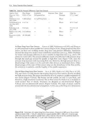
In-Plane Drag Force Flow Sensors Gass et al. [88], Nishimoto et al. [85], and Zhang et
al. [89] presented in-plane paddle flow sensors (Figure 9.24). Zhang proposed that their
sensor can have two working modes: drag force and pressure difference. Simulation
showed that drag force mode is more suitable for small flow rates (e.g., below 10 µl/min
for water) and pressure difference is more suitable for high flow rates (e.g., above 100
µl/min for water) [85]. The pressure difference mode is feasible due to the pressure drop
through the small gap around the paddle at high flow rates (Figure 9.24), since the
pressure drop increases with increasing flow rate. However, the high pressure drop is a
disadvantage if the sensor is to be used with other devices as mentioned above. Other
disadvantages of this type of flow sensor setup are the disturbance of the flow profile,
the sensitivity to particles, and the fragility of the paddle suspension.
Out-of-Plane Drag Force Flow Sensors Su et al. [90], Ozaki et al. [91], Fan et al. [92,
93], and Chen et al. [66] discuss out-of-plane drag force flow sensors, thereby avoiding
the high pressure drop. The sensor described by Su et al. employs a paddle suspended on
two beams [Figure 9.25(a)]. The beams and the paddle are only 2.5 µm thick, and
therefore, a high sensitivity is achieved. The air flow sensor by Ozaki et al. is modeled on
wind receptor hair of insects. Structures are designed as one-dimensional [Figure
9.26(a)] and two-dimensional sensors [Figure 9.26(b)]. The angle of attack could be
sensed with the two-dimensional arrangement. In this case, a thin long wire (dimensions
Flow
Piezoresistive
elements
Paddle
Figure 9.24 Schematic of in-plane drag force flow sensors. Zhang et al. [89] use a 10-µm-thick
2
2
cantilever beam (100 × 124 µm ) attached to a square paddle (500 × 500 µm ). A narrow gap
(200 mm) around the cantilever paddle forms a flow channel. The size of the cantilever beam for
2
the sensor by Gass et al. [88] was 1× 3 µm with a thickness of 10 µm.