Page 247 - MEMS Mechanical Sensors
P. 247

236                                                                    Flow Sensors

                                                                    Upstream
                                                           Frame    airfoil plate
                   Upstream                 Lift force
                   airfoil plate
           Flow
                                                           Center
                                                Drag force  support
                                                           beam                  Stress
                                                                                 concentrating
                       Central                             Piezo-                beam
                       support                             resistor
                       beam                   Downstream
                                              airfoil plate                       Downstream
                                                                                  airfoil plate
                              (a)                                       (b)
          Figure 9.27  Schematic of the lift force sensor: (a) side view, and (b) top view. The airfoil plates
                                             2
          are 15 µm thick and have an area of 5 × 5mm .(After: [95].)
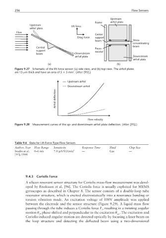
                                          Upstream airfoil
                                          Downstream airfoil
                                   deflection


                                   Airfoil


                                                      Flow velocity
          Figure 9.28  Measurement curves of the up- and downstream airfoil plate deflection. (After: [95].)


          Table 9.6  Data for Lift Force Type Flow Sensors
          Author; Year  Flow Range  Sensitivity    Response Time   Fluid       Chip Size
          Svedin et al.  0–6 m/s  7.4 (µV/V)/(m/s) 2  —            Gas         —
          [95]; 1998


                 9.4.3  Coriolis Force
                 A silicon resonant sensor structure for Coriolis mass-flow measurement was devel-
                 oped by Enoksson et al. [96]. The Coriolis force is usually exploited for MEMS
                 gyroscopes as described in Chapter 8. The sensor consists of a double-loop tube
                 resonator structure, which is excited electrostatically into a resonance bending or
                 torsion vibration mode. An excitation voltage of 100V amplitude was applied
                 between the electrode and the sensor structure (Figure 9.29). A liquid mass flow
                 passing through the tube induces a Coriolis force F , resulting in a twisting angular
                                                               c
                 motion θ , phase-shifted and perpendicular to the excitation θ . The excitation and
                         C                                              exc
                 Coriolis-induced angular motion are detected optically by focusing a laser beam on
                 the loop structure and detecting the deflected beam using a two-dimensional
   242   243   244   245   246   247   248   249   250   251   252