
Page 243 - MEMS Mechanical Sensors
P. 243
232 Flow Sensors
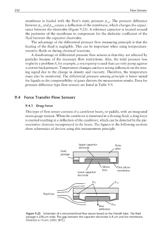
membrane is loaded with the flow’s static pressure p . The pressure difference
stat
between p and p causes a deflection of the membrane, which changes the capaci-
tot stat
tance between the electrodes (Figure 9.23). A reference capacitor is located around
the perimeter of the membrane to compensate for the dielectric coefficient of the
fluid between the capacitor electrodes.
The advantage of the differential pressure flow measuring principle is that the
heating of the fluid is negligible. This can be important when using temperature-
sensitive fluids or during chemical reactions.
A disadvantage of differential pressure flow sensors is that they are affected by
particles because of the necessary flow restrictions. Also, the total pressure loss
might be a problem if, for example, a micropump is used that can only pump against
a certain backpressure. Temperature changes can have strong influences on the sens-
ing signal due to the change in density and viscosity. Therefore, the temperature
must also be monitored. The differential pressure sensing principle is better suited
for liquids as the compressibility of gases distorts the measurement results. Data for
pressure difference type flow sensors are listed in Table 9.4.
9.4 Force Transfer Flow Sensors
9.4.1 Drag Force
This type of flow sensor consists of a cantilever beam, or paddle, with an integrated
strain gauge resistor. When the cantilever is immersed in a flowing fluid, a drag force
is exerted resulting in a deflection of the cantilever, which can be detected by the pie-
zoresistive elements incorporated in the beam. The figures in the following sections
show schematics of devices using this measurement principle.
Upper capacitor Pyrex
electrode glass
Fluid
passage
Silicon Thin silicon
boss membrane
Lower capacitor
electrode
p tot p stat
Fluid flow
p stat
Boss
deflection
Figure 9.23 Schematic of a micromachined flow sensor based on the Prandtl tube. The fluid
passage is 250 µm wide. The gap between the capacitor electrodes is 8 µm and the membrane
thickness is 14 µm. (After: [87].)